


12.2.3.2 Option rb/rm/rs
Parking a machine with a height-adjustable chassis and automatic jockey wheel
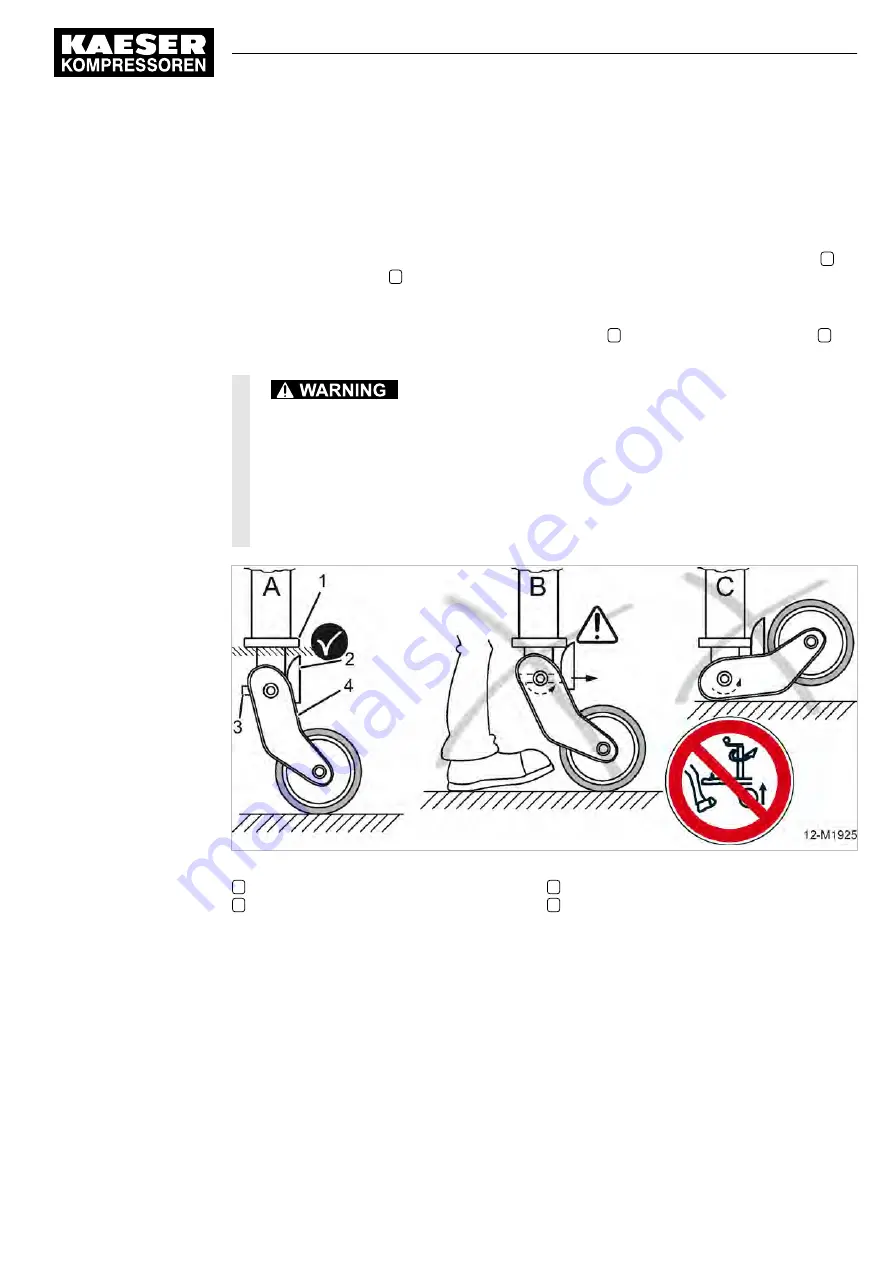
In a parked machine which is separated from the towing vehicle, the machine's bearing load affects
the automatic jockey wheel.
For this reason, the jockey wheel of a separated machine must be wound down until the cam
2
no
longer touches the bead
1
. The automatic folding of the wheel suspension is thus blocked (see
figure 82/A).
When the jockey wheel of a separated machine is wound up further, the bead pushes against the
cam of the retaining pin (see figure 82/B). The retaining pin
3
unlocks the wheel suspension
4
which will abruptly fold (see figure 82/C).
A folding wheel suspension during winding up causes the towing device to suddenly crash
onto the ground,
potentially causing severe injuries to legs and/or feet.
➤ Wind the automatic jockey wheel only up when the machine is coupled to a towing vehi‐
cle.
➤ Wind the automatic jockey wheel up only as far as the bead does not touch the cam.
➤ Do not place your feet beneath the towing device.
Fig. 82 Warning: Risk of injury due to falling towing device!
1
Bead
2
Cam
3
Retaining pin
4
Wheel suspension
1. Use a coupled towing vehicle to move the machine into position.
2. Place chocks under the wheels.
3. Loosen the lighting and signalling system.
4. Pull on the parking brake past the dead point zone (see figure 81).
The gas spring holds the brake under tension.
5. Detach the breakaway cable.
6. Lower the jockey wheel.
7. Pull the coupling handle up and lower the jockey wheel further.
The ball coupling must be released from the towing device of the towing vehicle.
12 Decommissioning, Storage and Transport
12.2 Transport
No.: 9_9548 05 USE
Operator Manual Screw Compressor
M27
227
Содержание M27
Страница 244: ...13 Annex 13 2 Pipeline and instrument flow diagram P I diagram 234 Operator Manual Screw Compressor M27 No 9_9548 05 USE...
Страница 245: ...13 Annex 13 2 Pipeline and instrument flow diagram P I diagram No 9_9548 05 USE Operator Manual Screw Compressor M27 235...
Страница 246: ...13 Annex 13 2 Pipeline and instrument flow diagram P I diagram 236 Operator Manual Screw Compressor M27 No 9_9548 05 USE...
Страница 260: ...13 Annex 13 4 Wiring diagrams 250 Operator Manual Screw Compressor M27 No 9_9548 05 USE...
Страница 261: ...13 Annex 13 4 Wiring diagrams No 9_9548 05 USE Operator Manual Screw Compressor M27 251...
Страница 262: ...13 Annex 13 4 Wiring diagrams 252 Operator Manual Screw Compressor M27 No 9_9548 05 USE...
Страница 263: ...13 Annex 13 4 Wiring diagrams No 9_9548 05 USE Operator Manual Screw Compressor M27 253...
Страница 264: ...13 Annex 13 4 Wiring diagrams 254 Operator Manual Screw Compressor M27 No 9_9548 05 USE...
Страница 265: ...13 Annex 13 4 Wiring diagrams No 9_9548 05 USE Operator Manual Screw Compressor M27 255...
Страница 266: ...13 Annex 13 4 Wiring diagrams 256 Operator Manual Screw Compressor M27 No 9_9548 05 USE...
Страница 267: ...13 Annex 13 4 Wiring diagrams No 9_9548 05 USE Operator Manual Screw Compressor M27 257...
Страница 268: ...13 Annex 13 4 Wiring diagrams 258 Operator Manual Screw Compressor M27 No 9_9548 05 USE...
Страница 270: ...13 Annex 13 4 Wiring diagrams 260 Operator Manual Screw Compressor M27 No 9_9548 05 USE...
Страница 271: ...13 Annex 13 4 Wiring diagrams No 9_9548 05 USE Operator Manual Screw Compressor M27 261...
Страница 272: ...13 Annex 13 4 Wiring diagrams 262 Operator Manual Screw Compressor M27 No 9_9548 05 USE...
Страница 273: ...13 Annex 13 4 Wiring diagrams No 9_9548 05 USE Operator Manual Screw Compressor M27 263...
Страница 274: ...13 Annex 13 4 Wiring diagrams 264 Operator Manual Screw Compressor M27 No 9_9548 05 USE...
Страница 276: ...13 Annex 13 4 Wiring diagrams 266 Operator Manual Screw Compressor M27 No 9_9548 05 USE...
Страница 277: ...13 Annex 13 4 Wiring diagrams No 9_9548 05 USE Operator Manual Screw Compressor M27 267...
Страница 278: ...13 Annex 13 4 Wiring diagrams 268 Operator Manual Screw Compressor M27 No 9_9548 05 USE...
Страница 279: ...13 Annex 13 4 Wiring diagrams No 9_9548 05 USE Operator Manual Screw Compressor M27 269...
Страница 281: ...13 Annex 13 4 Wiring diagrams No 9_9548 05 USE Operator Manual Screw Compressor M27 271...
Страница 282: ...13 Annex 13 4 Wiring diagrams 272 Operator Manual Screw Compressor M27 No 9_9548 05 USE...
Страница 283: ...13 Annex 13 4 Wiring diagrams No 9_9548 05 USE Operator Manual Screw Compressor M27 273...
Страница 284: ...13 Annex 13 4 Wiring diagrams 274 Operator Manual Screw Compressor M27 No 9_9548 05 USE...
Страница 286: ...13 Annex 13 4 Wiring diagrams 276 Operator Manual Screw Compressor M27 No 9_9548 05 USE...
Страница 287: ...13 Annex 13 4 Wiring diagrams No 9_9548 05 USE Operator Manual Screw Compressor M27 277...
Страница 288: ...13 Annex 13 4 Wiring diagrams 278 Operator Manual Screw Compressor M27 No 9_9548 05 USE...
Страница 289: ...13 Annex 13 4 Wiring diagrams No 9_9548 05 USE Operator Manual Screw Compressor M27 279...
Страница 290: ...13 Annex 13 5 Fuel circulation diagram No 9_9548 05 USE Operator Manual Screw Compressor M27 281...
Страница 291: ...13 Annex 13 5 Fuel circulation diagram 282 Operator Manual Screw Compressor M27 No 9_9548 05 USE...


