


Chapter 5 I/O Parameter
122
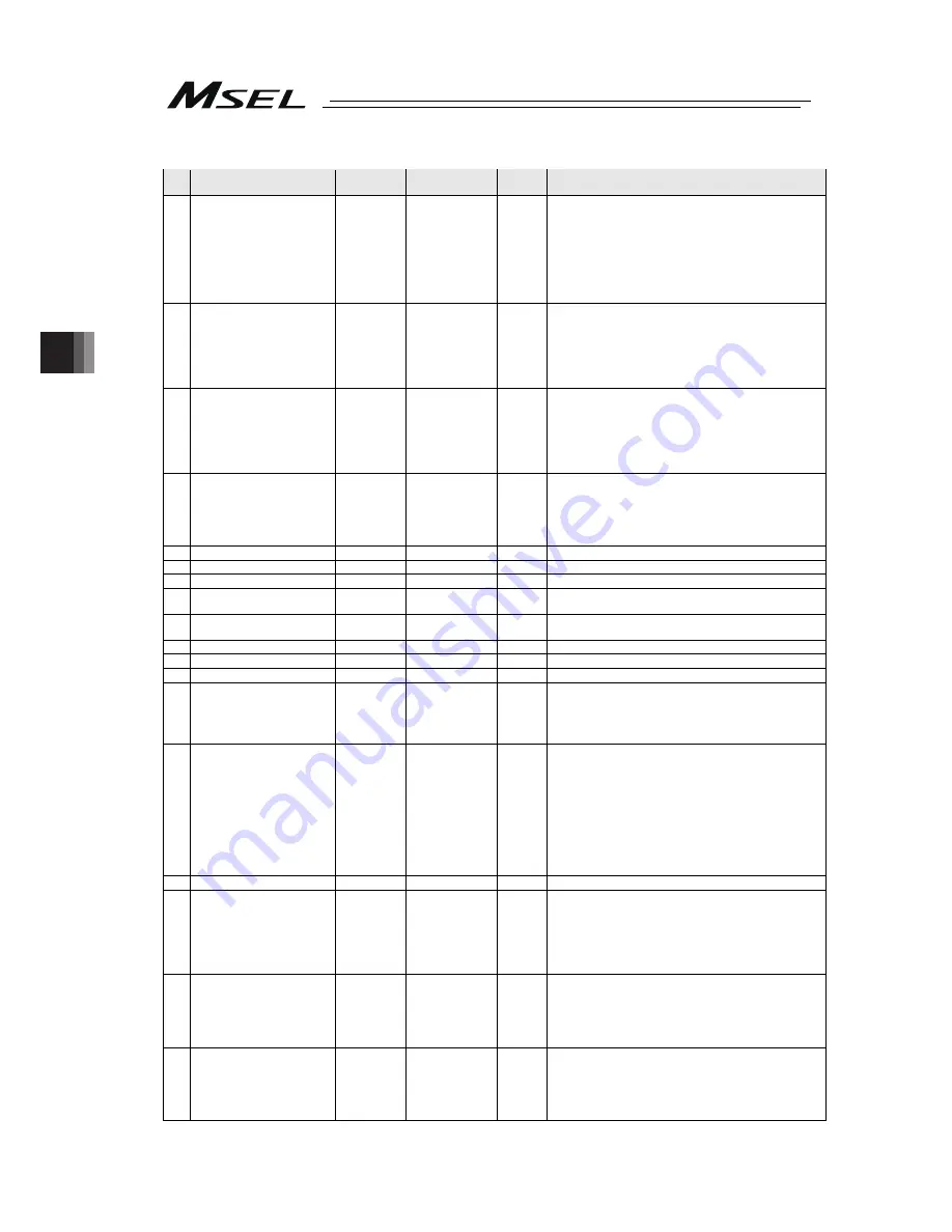
Axis-Specific Parameters
No.
Parameter name
Default value
(Reference)
Input range
Unit
Remarks
65
System reservation
(PCX/PGX type)
Synchro axis number of
mating axis
(PC/PG/PCF/PGF type)
0
0 ~ 8
* PCX/PGX is system reservation
Smaller axis number in a pair is the main axis. It is
available to indicate only when satisfying both that it is
the same characteristic axis in the resolution related and
that axis not necessary to have magnetic pole confirmed
operation. It is not available to issue any command to a
slave axis. (Ineffective at 0)
(Main application Ver. 2.00 and “V1” or later of last digits
of the manufacturing code)
66
Rotation movement axis mode
select
(PC/PG/PCF/PGF type)
Linear sliding axis rotation
movement axis mode select
(PCX/PGX type)
0
0 ~ 5
0: Normal
1: Index mode
* Valid only on linear sliding axes
67
Short-cut control selection for
rotational movement axis
(PC/PG/PCF/PGF type)
Short-cut control selection for
rotational movement axis
(PCX/PGX type)
0
0 ~ 5
0: Do not select
1: Select (effective when the specification is in index mode,
INC encode and simple absolute type)
* Valid only on linear sliding axes
68
Linear sliding axis mode select
(PC/PG/PCF/PGF type)
Linear sliding axis linear
sliding axis mode select
(PCX/PGX type)
0
0 ~ 5
0: Normal
1: Infinite-stroke mode
(Note: Positioning boundary applies. This setting can be
specified only when an incremental encoder is used.)
* Valid only on linear sliding axes
69 (For extension)
0
~
70 System reservation
32767
0 ~ 32767
DRVVR (Change prohibited)
71 System reservation
32767
0 ~ 32767
DRVVR (Change prohibited)
72 System reservation
1
-999 ~ 999
DRVVR
(Change prohibited) To maintain symmetry of the positive
and negative sides.
73 System reservation
0
-999 ~ 999
DRVVR
(Change prohibited) To maintain symmetry of the positive
and negative sides.
74 System reservation
32436
0 ~ 32767
DRVVR (Change prohibited)
75 System reservation
-32435
0 ~ -32767
DRVVR (Change prohibited)
76 System reservation
1
0 ~ 1
(Change prohibited)
77
System reservation
(PCX/PGX type)
Synchro S pulse
(PC/PG/PCF/PGF type)
0
(PCX/PGX)
3
(PC/PG/
PCF/PGF)
0 ~ 99999
pulse
* PCX/PGX is system reservation
(Main application Ver. 2.00 and “V1” or later of last digits
of the manufacturing code)
78
Maximum takeoff
command amount
0
-3000 ~ 3000
0.001mm
Maximum lift command amount before brake unlock (Input
with sign) (Suppression of momentary drop upon servo ON
when a heavy object is placed)
* Important:
Input using the same sign as the rising
coordinate direction. (0.100 mm to 0.500 mm in absolute
value as a guideline)
* The servo-ON check time (Axis-Specific Parameter No.
30) must also be extended (Approx. 1000 to 1500 msec)
to provide a sufficient time for rise-direction torque to
follow.
(Valid only when installation of brake is specified.)
79 Actual takeoff check distance
5
0 ~ 3000
0.001mm Absolute value input
80
Maximum compulsory feed
range
(PC/PG/PCF/PGF type)
Linear sliding axis Max.
compulsory feed range
(PCX/PGX type)
0
0 ~ 9999
0.001mm
For reduction of settling time.
(Invalid range if “0” is set)
(Approx. 1.000 mm as a guideline)
* Valid only on linear sliding axes
81
Min. compulsory feed range
(PC/PG/PCF/PGF type)
Linear sliding axis Min.
compulsory feed range
(PCX/PGX type)
200
0 ~ 9999
0.001mm * Valid only on linear sliding axes
82
Mid. compulsory feed range
(PC/PG/PCF/PGF type)
Linear sliding axis Mid.
compulsory feed range
(PCX/PGX type)
600
0 ~ 9999
0.001mm * Valid only on linear sliding axes
Содержание MSEL
Страница 1: ...MSEL Controller Instruction Manual Fifth Edition ...
Страница 2: ......
Страница 4: ......
Страница 30: ...22 ...
Страница 44: ...Chapter 1 Specifications Check 36 ...
Страница 102: ...Chapter 4 Home Return Absolute Reset 94 ...
Страница 232: ......
Страница 233: ......