7.
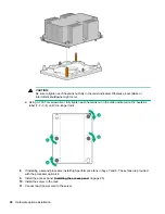
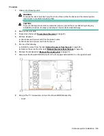
Remove the existing processor heatsink assembly:
a.
Allow the heatsink to cool.
b.
Using a T-30 Torx screwdriver, loosen the heatsink nuts.
c.
Lift the processor heatsink assembly up and away from the system board.
d.
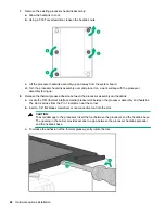
Turn the processor heatsink assembly over and place it on a work surface with the processor
assembly facing up.
8.
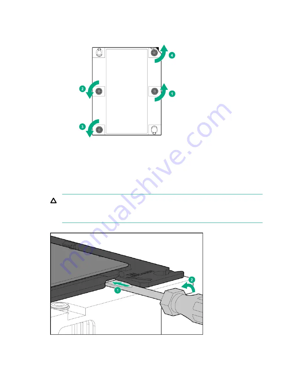
Release the thermal grease adhesion between the processor assembly and heatsink:
a.
Locate the TIM (thermal interface media) breaker slot between the processor assembly and heatsink.
The slot is across from the Pin 1 indicator, near the corner.
b.
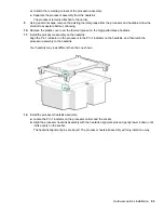
Insert a 1/4" flat blade screwdriver or nonconductive tool into the slot.
CAUTION:
To avoid damage to the processor, insert the tool between the processor and the heatsink base.
The opening in the carrier provides access to a gap between the processor heatsink spreader
and the heatsink base.
c.
To release the adhesion of the thermal grease, gently rotate the tool.
92
Hardware options installation
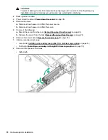
Содержание ProLiant DL360 Gen10
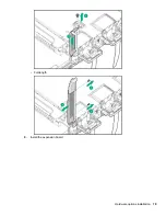
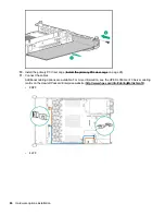
Страница 75: ...9 Install the full height PCIe x16 riser cage latch 10 Install the riser cage Hardware options installation 75 ...
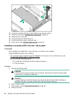
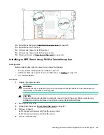
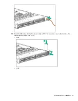
Страница 79: ... Full length 9 Install the expansion board Hardware options installation 79 ...
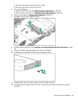
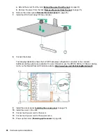
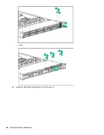
Страница 96: ... 4 LFF 9 Guide the SID cable through the front of the server 96 Hardware options installation ...

