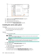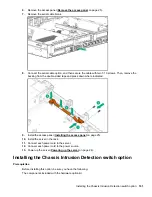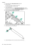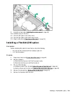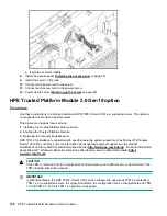
a.
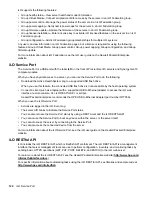
Disconnect each power cord from the power source.
b.
Disconnect each power cord from the server.
5.
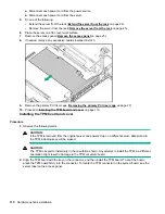
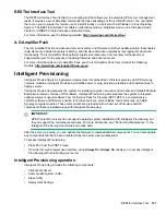
Do one of the following:
• Extend the server from the rack (
Extend the server from the rack
on page 24).
• Remove the server from the rack (
Remove the server from the rack
on page 25).
6.
Place the server on a flat, level work surface.
7.
8.
If needed, remove any expansion boards installed in slot 3.
9.
Remove the primary PCI riser cage (
Removing the primary PCI riser cage
on page 27).
10.
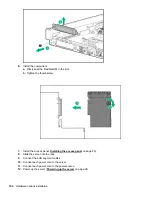
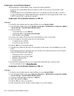
Installing the TPM board and cover
on page 110.
Installing the TPM board and cover
Procedure
1.
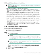
Observe the following alerts:
CAUTION:
If the TPM is removed from the original server and powered up on a different server, data stored in
the TPM including keys will be erased.
CAUTION:
The TPM is keyed to install only in the orientation shown. Any attempt to install the TPM in a different
orientation might result in damage to the TPM or system board.
2.
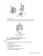
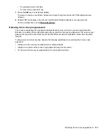
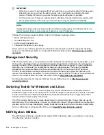
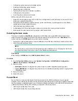
Align the TPM board with the key on the connector, and then install the TPM board. To seat the board,
press the TPM board firmly into the connector. To locate the TPM connector on the system board, see the
server label on the access panel.
110
Hardware options installation
Содержание ProLiant DL360 Gen10
Страница 75: ...9 Install the full height PCIe x16 riser cage latch 10 Install the riser cage Hardware options installation 75 ...
Страница 79: ... Full length 9 Install the expansion board Hardware options installation 79 ...
Страница 96: ... 4 LFF 9 Guide the SID cable through the front of the server 96 Hardware options installation ...

