background image

HPE ProLiant DL360 Gen10 Server User
Guide

Part Number: 869840-002
Published: September 2017
Edition: 2

Abstract

This document is for the person who installs, administers, and troubleshoots servers and storage
systems. Hewlett Packard Enterprise assumes you are qualified in the servicing of computer
equipment and trained in recognizing hazards in products with hazardous energy levels.

Содержание ProLiant DL360 Gen10

Страница 1: ...7 Edition 2 Abstract This document is for the person who installs administers and troubleshoots servers and storage systems Hewlett Packard Enterprise assumes you are qualified in the servicing of computer equipment and trained in recognizing hazards in products with hazardous energy levels ...

Страница 2: ...l computer software Valid license from Hewlett Packard Enterprise required for possession use or copying Consistent with FAR 12 211 and 12 212 Commercial Computer Software Computer Software Documentation and Technical Data for Commercial Items are licensed to the U S Government under vendor s standard commercial license Links to third party websites take you outside the Hewlett Packard Enterprise ...

Страница 3: ...e the server from the rack 25 Remove the access panel 25 Installing the access panel 25 Remove the hot plug fan 26 Removing the primary PCI riser cage 27 Install the primary PCI riser cage 28 Removing the secondary PCI riser cage 28 Install the secondary PCI riser cage 29 Removing the 8 SFF drive backplane 30 Releasing the cable management arm 31 Setup 32 Optional service 32 Optimum environment 32...

Страница 4: ...e option 61 Installing the rear drive riser cage option 63 Primary PCI riser cage options 66 Installing an optional primary PCI riser board 67 Installing the SATA M 2 2280 riser option 68 Installing an expansion board in the primary riser cage 70 Installing the primary GPU riser and cable option 71 Secondary PCI riser options 73 Installing a secondary full height PCI riser cage option 73 Installin...

Страница 5: ... iLO Federation 119 iLO Service Port 120 iLO RESTful API 120 RESTful Interface Tool 121 iLO Amplifier Pack 121 Intelligent Provisioning 121 Intelligent Provisioning operation 121 Management Security 122 Scripting Toolkit for Windows and Linux 122 UEFI System Utilities 122 Selecting the boot mode 123 Secure Boot 123 Launching the Embedded UEFI Shell 124 HPE Smart Storage Administrator 124 USB suppo...

Страница 6: ... 800W Flex Slot Universal Hot Plug Low Halogen Power Supply 136 HPE 800W Flex Slot 48VDC Hot Plug Low Halogen Power Supply 136 HPE 1600W Flex Slot Platinum Hot Plug Low Halogen Power Supply 137 Hot plug power supply calculations 138 Websites 139 Support and other resources 140 Accessing Hewlett Packard Enterprise Support 140 Accessing updates 140 Customer self repair 140 Remote support 141 Warrant...

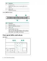
Страница 7: ...l drive optional 4 USB 2 0 port optional 5 USB 3 0 port 6 iLO Service Port The operating system does not recognize this port as a USB port 7 SAS SATA drive bays 4 LFF Item Description 1 Optical drive blank optional 2 Serial label pull tab 3 Display port optional 4 USB 2 0 port optional Table Continued Component identification 7 ...

Страница 8: ...SAS Combo Item Description 1 Serial label pull tab 2 Systems Insight Display optional 3 USB 3 0 port 4 SAS SATA NVMe drive bays When the 10SFF NVMe SAS backplane option is installed NVMe drives must be installed in bays 9 and 10 The other bays support a mix of NVMe and SAS drives Front panel LEDs and buttons 8SFF 10SFF 8 Front panel LEDs and buttons ...

Страница 9: ...id green Normal Flashing green iLO is rebooting Flashing amber System degraded Flashing red System critical 4 NIC status LED Solid green Link to network Flashing green Network active Off No network activity When all four LEDs described in this table flash simultaneously a power fault has occurred Facility power is not present power cord is not attached no power supplies are installed power supply ...

Страница 10: ...Solid green Normal Flashing green iLO is rebooting Flashing amber System degraded Flashing red System critical 4 Power On Standby button and system power LED Solid green System on Flashing green Performing power on sequence Solid amber System in standby Off No power present When all four LEDs described in this table flash simultaneously a power fault has occurred To identify components in a degrad...

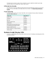
Страница 11: ...g table provides a list of power fault LEDs and the subsystems that are affected Not all power faults are used by all servers Subsystem LED behavior System board 1 flash Processor 2 flashes Memory 3 flashes Riser board PCIe slots 4 flashes FlexibleLOM 5 flashes Removable HPE Flexible Smart Array controller Smart SAS HBA controller 6 flashes System board PCIe slots 7 flashes Power backplane or stor...

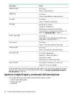
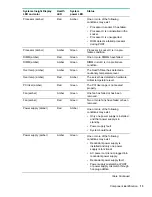
Страница 12: ...ge Over temp LED Off Normal Amber High system temperature detected Amp Status LED Off AMP modes disabled Solid green AMP mode enabled Solid amber Failover Flashing amber Invalid configuration Power cap LED Off System is in standby or no cap is set Solid green Power cap applied When the health LED on the front panel illuminates either amber or red the server is experiencing a health event For more ...

Страница 13: ...The server has detected a hardware critical temperature level PCI riser amber Red Green The PCI riser cage is not seated properly Fan amber Amber Green One fan has failed or has been removed Fan amber Red Green Two or more fans have failed or been removed Power supply amber Red Amber One or more of the following conditions may exist Only one power supply is installed and that power supply is in st...

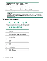
Страница 14: ...her troubleshooting is required Test each bank of DIMMs by removing all other DIMMs Isolate the failed DIMM by replacing each DIMM in a bank with a known working DIMM Rear panel components Item Description 1 Slot 1 PCIe3 2 Slot 2 PCIe3 3 Slot 3 PCIe3 optional requires second processor 4 Power supply 2 PS2 5 Power supply 1 PS1 6 Video port 7 NIC port 4 8 NIC port 3 9 NIC port 2 10 NIC port 1 11 iLO...

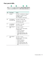
Страница 15: ... 2L iLO 5 standard NIC link LED Solid green Link exists Off No link exists 3 Power supply 2 LED Solid green Normal Off One or more of the following conditions exists AC power unavailable Power supply failed Power supply in standby mode Power supply exceeded current limit 4 Power supply 1 LED Solid green Normal Off One or more of the following conditions exists AC power unavailable Power supply fai...

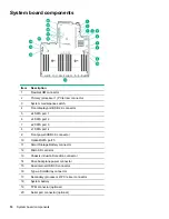
Страница 16: ... 3 8 x1 SATA port 4 9 Front power USB 3 0 connector 10 Optical SATA port 5 11 Smart Storage Battery connector 12 Micro SD card slot 13 Chassis Intrusion Detection connector 14 Drive backplane power connector 15 Dual internal USB 3 0 connector 16 Type a SmartArray connector 17 Secondary processor 2 PCIe riser connector 18 System battery 19 TPM connector optional 20 Serial port connector optional 16...

Страница 17: ...ot is enabled some configurations cannot be restored For more information see Secure Boot on page 123 NMI functionality An NMI crash dump enables administrators to create crash dump files when a system is hung and not responding to traditional debugging methods An analysis of the crash dump log is an essential part of diagnosing reliability problems such as hanging operating systems device drivers...

Страница 18: ...Device numbers 8SFF device bay numbering 8SFF 2 SFF device bay numbering Item Description 1 Box 1 bays 1 8 2 Box 2 bays 1 and 2 4LFF device bay numbering 18 Device numbers ...

Страница 19: ...mart Carrier M 2 SCM When the HPE SFF Flash Adapter is installed the uFF drives are recognized as 1 and 101 Hot plug drive LED definitions Item LED Status Definition 1 Locate Solid blue The drive is being identified by a host application Flashing blue The drive carrier firmware is being updated or requires an update 2 Activity ring Rotating green Drive activity Off No drive activity 3 Do not remov...

Страница 20: ... a RAID controller NVMe SSD components The NVMe SSD is a PCIe bus device A device attached to a PCIe bus cannot be removed without allowing the device and bus to complete and cease the signal traffic flow CAUTION Do not remove an NVMe SSD from the drive bay while the Do not remove LED is flashing The Do not remove LED flashes to indicate that the device is still in use Removing the NVMe SSD before...

Страница 21: ... not configured by a RAID controller 4 Do Not Remove LED Solid white Do not remove the drive Drive must be ejected from the PCIe bus prior to removal Flashing white Ejection request pending Off Drive has been ejected 5 Power LED Solid green Do not remove the drive Drive must be ejected from the PCIe bus prior to removal Flashing green Ejection request pending Off Drive has been ejected 6 Power but...

Страница 22: ...r is erasing Flashing amber green 1 Hz The drive is a member of one or more logical drives that predicts the drive will fail Solid amber The drive has failed Flashing amber 1 Hz The drive is not configured and predicts the drive will fail 5 Adapter ejection release latch and handle Removes the SFF flash adapter when released Hot plug fans CAUTION To avoid damage to server components fan blanks mus...

Страница 23: ...ed until a temperature change requires a fan speed increase to cool the server The server shuts down during the following temperature related scenarios At POST and in the OS iLO performs an orderly shutdown if a cautionary temperature level is detected If the server hardware detects a critical temperature level before an orderly shutdown occurs the server performs an immediate shutdown When the Th...

Страница 24: ...ng you can use this method to force a shutdown Use a virtual power button selection through iLO This method initiates a controlled remote shutdown of applications and the OS before the server enters standby mode Before proceeding verify that the server is in standby mode by observing that the system power LED is amber Extend the server from the rack NOTE If the optional cable management arm option...

Страница 25: ... the server on a sturdy level surface Remove the access panel WARNING To reduce the risk of personal injury from hot surfaces allow the drives and the internal system components to cool before touching them CAUTION Do not operate the server for long periods with the access panel open or removed Operating the server in this manner results in improper airflow and improper cooling that can lead to th...

Страница 26: ... within 60 seconds Otherwise the server will shut down gracefully 2 Do one of the following a Extend the server from the rack Extend the server from the rack on page 24 b Remove the server from the rack Remove the server from the rack on page 25 3 Remove the access panel Remove the access panel on page 25 4 Remove the fan 26 Remove the hot plug fan ...

Страница 27: ...boards power down the server and remove all AC power cords before removing or installing the PCI riser cage Procedure 1 Back up all server data 2 Power down the server Power down the server on page 24 3 Remove all power a Disconnect each power cord from the power source b Disconnect each power cord from the server 4 Do one of the following a Extend the server from the rack Extend the server from t...

Страница 28: ...wer cords before removing or installing the PCI riser cage 2 Back up all server data 3 Power down the server Power down the server on page 24 4 Remove all power a Disconnect each power cord from the power source b Disconnect each power cord from the server 5 Do one of the following a Extend the server from the rack Extend the server from the rack on page 24 b Remove the server from the rack Remove...

Страница 29: ...10 Remove the PCI riser cage Install the secondary PCI riser cage Procedure 1 Install the PCI riser cage Install the secondary PCI riser cage 29 ...

Страница 30: ...all server data 2 Power down the server Power down the server on page 24 3 Remove all power a Disconnect each power cord from the power source b Disconnect each power cord from the server 4 Do one of the following a Extend the server from the rack Extend the server from the rack on page 24 b Remove the server from the rack Remove the server from the rack on page 25 5 Remove the access panel Remove...

Страница 31: ...Releasing the cable management arm Release the cable management arm and then swing the arm away from the rack Releasing the cable management arm 31 ...

Страница 32: ...e Education Services Help train your IT staff 1The time commitment for this repair service might vary depending on the site s geographical region For more service information available in your site contact your local Hewlett Packard Enterprise support center For more information on Hewlett Packard Enterprise support services see the Hewlett Packard Enterprise website Optimum environment When insta...

Страница 33: ...0 sq in of holes evenly distributed from top to bottom to permit adequate airflow equivalent to the required 64 percent open area for ventilation Side The clearance between the installed rack component and the side panels of the rack must be a minimum of 7 cm 2 75 in IMPORTANT The Hewlett Packard Enterprise DL360 Gen10 Server cable management arm is not supported on Compaq branded 7000 series rack...

Страница 34: ...he installation such as branch wiring and receptacles are listed or certified grounding type devices Because of the high ground leakage currents associated with multiple servers connected to the same power source Hewlett Packard Enterprise recommends the use of a PDU that is either permanently wired to the building s branch circuit or includes a nondetachable cord that is wired to an industrial st...

Страница 35: ...ires IMPORTANT The ring terminals must be UL approved and accommodate 12 gauge wires IMPORTANT The minimum nominal thread diameter of a pillar or stud type terminal must be 3 5 mm 0 138 in the diameter of a screw type terminal must be 4 0 mm 0 157 in 3 Stack each same colored pair of wires and then attach them to the same power source The power cord consists of three wires black red and green For ...

Страница 36: ...ions Screwdriver Installing hardware options Install any hardware options before initializing the server For options installation information refer to the option documentation For server specific information refer to Hardware options installation Installing the server into the rack To install the server into a rack with square round or threaded holes refer to the instructions that ship with the ra...

Страница 37: ...ackard Enterprise website To install an operating system on the server use one of the following methods Intelligent Provisioning For single server deployment updating and provisioning capabilities For more information see Installing the operating system with Intelligent Provisioning on page 37 Insight Control server provisioning For multiserver remote OS deployment use Insight Control server provi...

Страница 38: ...erver supports both Legacy BIOS Boot Mode and UEFI Boot Mode On servers operating in UEFI Boot Mode the boot controller and boot order are set automatically Procedure 1 Press the Power On Standby button 2 Do one of the following a To enter the UEFI System Utilities screen and modify the server configuration ROM default settings press the F9 key on the ProLiant POST screen Choose one of the followi...

Страница 39: ...roper grounding can cause electrostatic discharge Installing a redundant hot plug power supply Prerequisites Before installing this option be sure you have the following The components included with the hardware option kit Procedure 1 Observe the following alerts CAUTION All power supplies installed in the server must have the same output power capacity Verify that all power supplies have the same...

Страница 40: ...ear panel LEDs on page 15 Memory options IMPORTANT This server does not support mixing LRDIMMs and RDIMMs Attempting to mix any combination of these DIMMs can cause the server to halt during BIOS initialization All memory installed in the server must be of the same type DIMM population information For specific DIMM population information see the DIMM population guidelines on the Hewlett Packard En...

Страница 41: ... to locate specific information about the DIMM Item Description Definition 1 Capacity 8 GB 16 GB 32 GB 64 GB 128 GB 2 Rank 1R Single rank 2R Dual rank 4R Quad rank 8R Octal rank 3 Data width on DRAM x4 4 bit x8 8 bit x16 16 bit 4 Memory generation PC4 DDR4 5 Maximum memory speed 2133 MT s 2400 MT s 2666 MT s Table Continued DIMM label identification 41 ...

Страница 42: ...alling this option be sure you have the following The components included with the hardware option kit For more information on specific options see the server QuickSpecs on the Hewlett Packard Enterprise website Procedure 1 Power down the server Power down the server on page 24 2 Remove all power a Disconnect each power cord from the power source b Disconnect each power cord from the server 3 Do o...

Страница 43: ...onfigurations see the Hewlett Packard Enterprise website The high performance fans are used for 8 SFF and 10 SFF drive configurations They are also required for the 10 SFF SAS SATA NVMe Combo backplane option and for ASHRAE compliant configurations For more information on ASHRAE compliant configurations see the Hewlett Packard Enterprise website Prerequisites Before installing this option be sure ...

Страница 44: ... on page 25 5 Remove the access panel Remove the access panel on page 25 6 Remove all standard fans from the fan bays 7 Remove fan blanks from the fan bays if installed 8 Install high performance fans in each of the seven fan bays If needed ensure each fan is securely installed by pressing the tab Do not press on other areas of the fan 44 Hardware options installation ...

Страница 45: ...ally sets all device numbers If only one hard drive is used install it in the bay with the lowest device number Drives should be the same capacity to provide the greatest storage space efficiency when drives are grouped together into the same drive array Hot plug drive guidelines When adding drives to the server observe the following general guidelines The system automatically sets all device numb...

Страница 46: ...equisites Before installing this option be sure that you have the following The components included with the hardware option kit Procedure 1 Remove the drive blank 2 Prepare the drive 3 Install the drive 46 Installing a hot plug SAS or SATA drive ...

Страница 47: ... up all server data on the drive 3 Remove the drive Installing the NVMe drives NVMe drives are supported in 8 SFF and 10 SFF server configurations when the 10 SFF SAS SATA NVMe Combo backplane option or the 2 SFF NVMe backplane option is installed When either backplane is installed NVMe drives are required in bays 9 and 10 For more information see Device numbers on page 18 Prerequisites NVMe drive...

Страница 48: ...lled 3 Press the Do Not Remove button to open the release handle 4 Install the drives 5 Install an SFF drive blank in any unused drive bays Removing and replacing an NVMe drive An NVMe SSD is a PCIe BUS device Devices attached to a PCIe bus cannot be removed without allowing the device and the bus to complete and cease signal traffic flow 48 Removing and replacing an NVMe drive ...

Страница 49: ... stops and the Do Not Remove button is no longer illuminated c Push the Do Not Remove button and then remove the drive Installing a uFF drive and SCM drive carrier IMPORTANT Not all drive bays support the drive carrier To find supported bays see the server QuickSpecs Procedure 1 If needed install the uFF drive into the drive carrier 2 Remove the drive blank 3 Install the drives Installing a uFF dr...

Страница 50: ...n the server To configure the drive use HPE Smart Storage Administrator Removing and replacing a uFF drive Procedure 1 Back up all server data 2 Observe the LED status of the drive and determine if it can be removed 3 Remove the drive To remove the drive carrier 50 Removing and replacing a uFF drive ...

Страница 51: ... an optical drive be sure the 8 SFF display port USB optical blank option is installed For more information see Installing an 8 SFF display port USB optical blank option on page 59 Procedure 1 Remove the optical drive blank 2 Install the optical drive 3 Connect the optical drive cable Installing an 8 SFF optical drive 51 ...

Страница 52: ...ing The components included with the hardware option kit T 10 Torx screwdriver Additional cables as needed For more information see SFF cables on page 114 2 SFF SAS or SATA drives or blanks For more information contact a Hewlett Packard Enterprise authorized reseller Procedure 1 Back up all server data 2 Power down the server Power down the server on page 24 3 Remove all power a Disconnect each po...

Страница 53: ... standard cable routing for this component For more information on optional cable routing see the Hewlett Packard Enterprise DL360 Gen10 Server cabling matrix on the Hewlett Packard Enterprise website http www hpe com info CablingMatrixGen10 9 Route and connect the data cable Hardware options installation 53 ...

Страница 54: ...ower source 15 Power up the server Powering up the server on page 24 16 Install drives Installing a 2 SFF NVMe drive cage option Prerequisites Before installing this option be sure that you have the following The components included with the hardware option kit T 10 Torx screwdriver Additional cables as needed For more information see SFF cables on page 114 NVMe drives 54 Installing a 2 SFF NVMe d...

Страница 55: ...the server 4 Do one of the following a Extend the server from the rack Extend the server from the rack on page 24 b Remove the server from the rack Remove the server from the rack on page 25 5 Remove the access panel Remove the access panel on page 25 6 Remove the universal media bay blank 7 Install the 2 SFF NVMe drive cage 8 Remove the primary PCI riser cage Removing the primary PCI riser cage o...

Страница 56: ...l cable routing see the Hewlett Packard Enterprise DL360 Gen10 Server cabling matrix on the Hewlett Packard Enterprise website http www hpe com info CablingMatrixGen10 12 Route and connect the data cable 13 Install the primary PCI riser cage 14 Install the access panel Installing the access panel on page 25 15 Install the server in the rack 16 Connect each power cord to the server 56 Hardware opti...

Страница 57: ...e option kit T 10 Torx screwdriver Additional cables as needed For more information see SFF cables on page 114 2 SFF SAS SATA drives 4 uFF M 2 drives or blanks For more information contact a Hewlett Packard Enterprise authorized reseller Procedure 1 Back up all server data 2 Power down the server Power down the server on page 24 3 Remove all power a Disconnect each power cord from the power source...

Страница 58: ...nent For more information on optional cable routing see the Hewlett Packard Enterprise DL360 Gen10 Server cabling matrix on the Hewlett Packard Enterprise website http www hpe com info CablingMatrixGen10 9 Route and connect the data cable 10 Route and connect the power cable 58 Hardware options installation ...

Страница 59: ...crewdriver An optical drive if installing For more information contact a Hewlett Packard Enterprise authorized reseller Procedure 1 Back up all server data 2 Power down the server Power down the server on page 24 3 Remove all power a Disconnect each power cord from the power source b Disconnect each power cord from the server 4 Do one of the following a Extend the server from the rack Extend the s...

Страница 60: ...7 Install the 8 SFF display port USB optical blank option 8 Route and connect the data cable 60 Hardware options installation ...

Страница 61: ... option kit T 10 Torx screwdriver LFF optical cable option kit An optical drive For more information contact a Hewlett Packard Enterprise authorized reseller Procedure 1 Back up all server data 2 Power down the server Power down the server on page 24 3 Remove all power a Disconnect each power cord from the power source b Disconnect each power cord from the server 4 Do one of the following a Extend...

Страница 62: ...r more information on optional cable routing see the Hewlett Packard Enterprise DL360 Gen10 Server cabling matrix on the Hewlett Packard Enterprise website http www hpe com info CablingMatrixGen10 9 Connect the optical drive cable to the optical drive backplane and to the SATA optical storage drive connector 62 Hardware options installation ...

Страница 63: ...kit T 10 and T 15 Torx screwdriver 1 SFF drive 2 uFF M 2 drives or blanks Procedure 1 Power down the server Power down the server on page 24 2 Remove all power a Disconnect each power cord from the power source b Disconnect each power cord from the server 3 Do one of the following a Extend the server from the rack Extend the server from the rack on page 24 b Remove the server from the rack Remove ...

Страница 64: ...oard Set aside for later use 8 If installed remove the slot 2 bracket from the primary riser cage 9 If needed install the riser board removed in step 7 on the rear drive riser cage bracket 64 Hardware options installation ...

Страница 65: ...l the riser cage bracket on the rear drive riser cage 12 If needed install an expansion board Installing an expansion board in the primary riser cage on page 70 13 Install the rear drive riser cage in the primary riser cage position Hardware options installation 65 ...

Страница 66: ...ablingMatrixGen10 15 Install drives or blanks Drive options on page 45 16 Install the access panel Installing the access panel on page 25 17 Install the server in the rack 18 Power up the server Powering up the server on page 24 19 Connect each power cord to the server 20 Connect each power cord to the power source Primary PCI riser cage options The primary PCI riser cage supports the following Sl...

Страница 67: ...er a Disconnect each power cord from the power source b Disconnect each power cord from the server 4 Do one of the following a Extend the server from the rack Extend the server from the rack on page 24 b Remove the server from the rack Remove the server from the rack on page 25 5 Remove the access panel Remove the access panel on page 25 6 Remove the primary PCI riser cage Removing the primary PCI...

Страница 68: ...s Before installing this option be sure that you have the following The components included with the hardware option kit Up to two 2280 form factor M 2 drives T 15 Torx screwdriver Procedure 1 Power down the server Power down the server on page 24 2 Remove all power a Disconnect each power cord from the power source b Disconnect each power cord from the server 3 Do one of the following a Extend th...

Страница 69: ...isting riser board from the riser cage 8 Install the M 2 riser board 9 Remove the screw securing the standoff on the riser 10 Install the M 2 drives 11 Install the following as needed Hardware options installation 69 ...

Страница 70: ...system components to cool before touching them CAUTION To prevent damage to electrical components properly ground the server before beginning any installation procedure Improper grounding can cause electrostatic discharge 2 Back up all server data 3 Power down the server Power down the server on page 24 4 Remove all power a Disconnect each power cord from the power source b Disconnect each power c...

Страница 71: ...to the server 15 Connect each power cord to the power source 16 Power up the server Powering up the server on page 24 Installing the primary GPU riser and cable option Prerequisites This option requires the standard primary PCI riser cage Before installing this option be sure that the power supplies support the installation of this option For more information see the Hewlett Packard Enterprise Con...

Страница 72: ...erver Power down the server on page 24 4 Remove all power a Disconnect each power cord from the power source b Disconnect each power cord from the server 5 Do one of the following a Extend the server from the rack Extend the server from the rack on page 24 b Remove the server from the rack Remove the server from the rack on page 25 6 Remove the access panel Remove the access panel on page 25 7 Rem...

Страница 73: ...or configuration Before installing this option be sure you have the following The components included with the hardware option kit Any expansion boards or controllers you plan to install Procedure 1 Power down the server Power down the server on page 24 2 Remove all power a Disconnect each power cord from the power source b Disconnect each power cord from the server 3 Do one of the following a Ext...

Страница 74: ...7 If installed remove the low profile riser cage 8 Lift and remove the secondary riser cage latch 74 Hardware options installation ...

Страница 75: ...9 Install the full height PCIe x16 riser cage latch 10 Install the riser cage Hardware options installation 75 ...

Страница 76: ...es an additional low profile slot and supports half length half height expansion boards Prerequisites This option requires a dual processor configuration Before installing this option be sure that you have the following The components included with the hardware option kit Procedure 1 Observe the following alerts WARNING To reduce the risk of personal injury from hot surfaces allow the drives and t...

Страница 77: ...roller options on page 82 9 Install the access panel Installing the access panel on page 25 10 Install the server into the rack Installing the server into the rack on page 36 11 Connect each power cord to the server 12 Connect each power cord to the power source 13 Power up the server Powering up the server on page 24 Installing an expansion board in the secondary riser cage Prerequisites Before i...

Страница 78: ... power cord from the server 5 Do one of the following a Extend the server from the rack Extend the server from the rack on page 24 b Remove the server from the rack Remove the server from the rack on page 25 6 Remove the access panel Remove the access panel on page 25 7 Install a secondary riser cage Low profile Installing a secondary low profile PCIe slot riser cage option on page 76 Full height ...

Страница 79: ... Full length 9 Install the expansion board Hardware options installation 79 ...

Страница 80: ...upport the installation of this option For more information see the Hewlett Packard Enterprise Configurator website Be sure you have the following items The components included with the GPU enablement option kit T 10 Torx screwdriver Procedure 1 Observe the following alerts WARNING To reduce the risk of personal injury from hot surfaces allow the drives and the internal system components to cool b...

Страница 81: ... on page 25 7 If installed remove the low profile riser cage 8 Install the GPU enabled riser cage Installing a secondary full height PCI riser cage option on page 73 9 Remove the existing rear guide bracket from the GPU if installed 10 If installing a 3 4 length GPU install the bracket supplied in the kit 11 Install the GPU in the riser cage and then connect the cable to the GPU 12 If installing a...

Страница 82: ...re option kit T 15 Torx screwdriver Procedure 1 Observe the following alerts WARNING To reduce the risk of personal injury from hot surfaces allow the drives and the internal system components to cool before touching them CAUTION To prevent damage to electrical components properly ground the server before beginning any installation procedure Improper grounding can cause electrostatic discharge 2 B...

Страница 83: ...move the access panel Remove the access panel on page 25 7 Install the controller 8 Connect the cables Additional cabling options are available For more information see the HPE DL360 Gen10 Server cabling matrix on the Hewlett Packard Enterprise website http www hpe com info CablingMatrixGen10 8 SFF 10 SFF SAS SATA NVMe Combo Hardware options installation 83 ...

Страница 84: ...the power source 13 Power up the server Powering up the server on page 24 Installing an HPE Smart Array P408i p Controller option Prerequisites Before installing this option be sure you have the following The components included with the hardware option kit T 15 Torx screwdriver Procedure 1 Observe the following alerts 84 Installing an HPE Smart Array P408i p Controller option ...

Страница 85: ...Power down the server on page 24 4 Remove all power a Disconnect each power cord from the power source b Disconnect each power cord from the server 5 Do one of the following a Extend the server from the rack Extend the server from the rack on page 24 b Remove the server from the rack Remove the server from the rack on page 25 6 Remove the access panel Remove the access panel on page 25 7 Remove th...

Страница 86: ...ge on page 28 11 Connect the cables Additional cabling options are available For more information see the HPE DL360 Gen10 Server cabling matrix on the Hewlett Packard Enterprise website http www hpe com info CablingMatrixGen10 8 SFF 4 LFF 86 Hardware options installation ...

Страница 87: ...ee Cabling on page 114 T 15 Torx screwdriver Procedure 1 Observe the following alerts WARNING To reduce the risk of personal injury from hot surfaces allow the drives and the internal system components to cool before touching them CAUTION To prevent damage to electrical components properly ground the server before beginning any installation procedure Improper grounding can cause electrostatic disc...

Страница 88: ...2 SFF backplane configuration connected to the controller Additional cabling options are available For more information see the HPE DL360 Gen10 Server cabling matrix on the Hewlett Packard Enterprise website http www hpe com info CablingMatrixGen10 9 Install the access panel Installing the access panel on page 25 10 Install the server in the rack 11 Connect each power cord to the server 12 Connect...

Страница 89: ...e the Hewlett Packard Enterprise Support Center website CAUTION THE CONTACTS ARE VERY FRAGILE AND EASILY DAMAGED To avoid damage to the socket or processor do not touch the contacts 2 Power down the server Power down the server on page 24 3 Remove all power a Disconnect each power cord from the power source b Disconnect each power cord from the server 4 Remove the server from the rack Remove the s...

Страница 90: ...nk nut in the order indicated on the heatsink label 1 2 3 4 until it no longer turns 8 If installing a second processor install high performance fans in bays 7 and 8 These fans are provided with the processor option kit 9 Install the access panel Installing the access panel on page 25 10 Install the server in the rack 11 Connect each power cord to the server 90 Hardware options installation ...

Страница 91: ... When handling the heatsink always hold it along the top and bottom of the fins Holding it from the sides can damage the fins CAUTION THE CONTACTS ARE VERY FRAGILE AND EASILY DAMAGED To avoid damage to the socket or processor do not touch the contacts 2 Power down the server Power down the server on page 24 3 Remove all power a Disconnect each power cord from the power source b Disconnect each pow...

Страница 92: ...essor assembly and heatsink a Locate the TIM thermal interface media breaker slot between the processor assembly and heatsink The slot is across from the Pin 1 indicator near the corner b Insert a 1 4 flat blade screwdriver or nonconductive tool into the slot CAUTION To avoid damage to the processor insert the tool between the processor and the heatsink base The opening in the carrier provides acc...

Страница 93: ... processor assembly on the heatsink Align the Pin 1 indicator on the processor to the Pin 1 indicator on the heatsink and then latch the processor assembly to the heatsink Your heatsink may look different than the one shown 12 Install the processor heatsink assembly a Locate the Pin 1 indicator on the processor carrier and the socket b Align the processor heatsink assembly with the heatsink alignm...

Страница 94: ...ing a T 30 Torx screwdriver fully tighten each heatsink nut until it no longer turns Installing the Systems Insight Display power module Prerequisites Before installing this option be sure you have the following The components included with the hardware option kit T 10 Torx screwdriver 94 Installing the Systems Insight Display power module ...

Страница 95: ...n the server Power down the server on page 24 4 Remove all power a Disconnect each power cord from the power source b Disconnect each power cord from the server 5 Do one of the following a Extend the server from the rack Extend the server from the rack on page 24 b Remove the server from the rack Remove the server from the rack on page 25 6 Remove the access panel Remove the access panel on page 2...

Страница 96: ... 4 LFF 9 Guide the SID cable through the front of the server 96 Hardware options installation ...

Страница 97: ...10 Install the SID module into the front panel Using a T 10 Torx screwdriver secure the module to the chassis with the screws from the kit 8 SFF 4 LFF Hardware options installation 97 ...

Страница 98: ...is option be sure you have the following The components included with the hardware option kit T 10 Torx screwdriver Procedure 1 Power down the server Power down the server on page 24 2 Remove all power a Disconnect each power cord from the power source b Disconnect each power cord from the server 3 Do one of the following 98 Installing the 4 LFF display port USB module ...

Страница 99: ... from the rack Remove the server from the rack on page 25 4 Remove the access panel Remove the access panel on page 25 5 Using a Torx T 10 screwdriver remove the 4 LFF display port USB blank 6 Install the 4 LFF display port USB module 7 Route and connect the cable Hardware options installation 99 ...

Страница 100: ...rsonal injury from hot surfaces allow the drives and the internal system components to cool before touching them CAUTION To prevent damage to electrical components properly ground the server before beginning any installation procedure Improper grounding can cause electrostatic discharge 2 Back up all server data 3 Power down the server Power down the server on page 24 4 Remove all power a Disconne...

Страница 101: ...cess panel Installing the access panel on page 25 10 Install the server in the rack 11 Connect each power cord to the server 12 Connect each power cord to the power source 13 Power up the server Powering up the server on page 24 Installing the Chassis Intrusion Detection switch option Prerequisites Before installing this option be sure you have the following The components included with the hardwa...

Страница 102: ...r from the rack on page 24 b Remove the server from the rack Remove the server from the rack on page 25 4 Remove the access panel Remove the access panel on page 25 5 Remove the left DIMM guard from the system board 6 Assemble the connector cable harness pin openings to the alignment pegs on the DIMM guard 7 Install the plastic cover on the DIMM guard 8 Install the DIMM guard and then connect the ...

Страница 103: ...omponents included with the hardware option kit T 15 Torx screwdriver Procedure 1 Power down the server Power down the server on page 24 2 Remove all power a Disconnect each power cord from the power source b Disconnect each power cord from the server 3 Do one of the following a Extend the server from the rack Extend the server from the rack on page 24 b Remove the server from the rack Remove the ...

Страница 104: ... the access panel Installing the access panel on page 25 8 Slide the server into the rack 9 Connect the LAN segment cables 10 Connect each power cord to the server 11 Connect each power cord to the power source 12 Power up the server Powering up the server on page 24 104 Hardware options installation ...

Страница 105: ... Procedure 1 Power down the server Power down the server on page 24 2 Remove all power a Disconnect each power cord from the power source b Disconnect each power cord from the server 3 Do one of the following a Extend the server from the rack Extend the server from the rack on page 24 b Remove the server from the rack Remove the server from the rack on page 25 4 Remove the access panel Remove the ...

Страница 106: ...h power cord from the power source b Disconnect each power cord from the server 3 Do one of the following a Extend the server from the rack Extend the server from the rack on page 24 b Remove the server from the rack Remove the server from the rack on page 25 4 Remove the access panel Remove the access panel on page 25 5 Remove the right retainer Set aside 6 Slide the battery into the left retaine...

Страница 107: ...7 Connect the cable a Remove the center fan baffle b Connect the Smart Storage battery cable to the extender cable Hardware options installation 107 ...

Страница 108: ...TPM 2 0 installation is supported with specific operating system support such as Microsoft Windows Server 2012 R2 and later For more information about operating system support see the product QuickSpecs on the Hewlett Packard Enterprise website http www hpe com info qs For more information about Microsoft Windows BitLocker Drive Encryption feature see the Microsoft website http www microsoft com C...

Страница 109: ...very key password The recovery key password is required to complete Recovery Mode after BitLocker detects a possible compromise of system integrity or system configuration Hewlett Packard Enterprise is not liable for blocked data access caused by improper TPM use For operating instructions see the TPM documentation or the encryption technology feature documentation provided by the operating system...

Страница 110: ...10 Proceed to Installing the TPM board and cover on page 110 Installing the TPM board and cover Procedure 1 Observe the following alerts CAUTION If the TPM is removed from the original server and powered up on a different server data stored in the TPM including keys will be erased CAUTION The TPM is keyed to install only in the orientation shown Any attempt to install the TPM in a different orient...

Страница 111: ...r for operation on page 111 Preparing the server for operation Procedure 1 Install any options or cables previously removed to access the TPM connector 2 Install the access panel 3 Do one of the following a Install the server in the rack if necessary b Install the server in the enclosure 4 Power up the server a Connect the power cords rack and tower servers b Press the Power On Standby button Hard...

Страница 112: ...ssed in the previous step do one of the following If in graphical mode click Yes If in text mode press the Y key 6 Press the ESC key to exit System Utilities 7 If changes were made and saved the server prompts for reboot request Press the Enter key to confirm reboot If the following actions were performed the server reboots a second time without user input During this reboot the TPM setting become...

Страница 113: ...enerated during BitLocker setup and can be saved and printed after BitLocker is enabled When using BitLocker always retain the recovery key password The recovery key password is required to enter Recovery Mode after BitLocker detects a possible compromise of system integrity To help ensure maximum security observe the following guidelines when retaining the recovery key password Always store the r...

Страница 114: ...1 874615 001 8 SFF SAS SATA Backplane Type p Smart Array Controller Slot 2 2 SFF Backplane Option Kit 876867 001 2 SFF SAS SATA Backplane Embedded SATA Type p Smart Array Controller 869669 001 2 SFF SAS SATA Backplane P816i a Smart Array Controller 2 SFF SCM Backplane Option Kit 869668 001 2 SFF SCM Backplane Embedded SATA 869669 001 2 SFF SCM Backplane P816i a Smart Array Controller 2 SFF SCM Bac...

Страница 115: ...OTE The following information describes the standard cable routing for this component For more information on optional cable routing see the Hewlett Packard Enterprise DL360 Gen10 Server cabling matrix on the Hewlett Packard Enterprise website http www hpe com info CablingMatrixGen10 8 SFF backplane to P408i a controller 2 SFF backplane to P816i a controller SFF configuration cable routing 115 ...

Страница 116: ...ling matrix on the Hewlett Packard Enterprise website http www hpe com info CablingMatrixGen10 8 SFF backplane to P408i p controller 8 SFF backplane to system board SATA 8 SFF backplane power cable 2 SFF backplane to P408i p controller 2 SFF backplane to system board SATA 2 SFF to 8 SFF power cable 1 SFF rear backplane to P816i a controller SFF system power USB cable 116 2 SFF NVMe backplane to pr...

Страница 117: ...ation describes the standard cable routing for this component For more information on optional cable routing see the Hewlett Packard Enterprise DL360 Gen10 Server cabling matrix on the Hewlett Packard Enterprise website http www hpe com info CablingMatrixGen10 4 LFF backplane to P408i a controller Additional LFF cabling For more information on the following cables and cabling configurations see th...

Страница 118: ...ct features specifications options configurations and compatibility see the product QuickSpecs on the Hewlett Packard Enterprise website http www hpe com info qs Active Health System Viewer Active Health System Viewer AHSV is an online tool used to read diagnose and resolve server issues quickly using AHS uploaded data AHSV provides Hewlett Packard Enterprise recommended repair actions based on ex...

Страница 119: ... collected is managed according to the privacy statement available at http www hpe com info privacy You can also upload the log to the Active Health System Viewer For more information see the Active Health System Viewer documentation at the following website http www hpe com support ahsv docs HPE iLO 5 iLO 5 is a remote server management processor embedded on the system boards of HPE ProLiant serv...

Страница 120: ...When you use this feature the connected USB flash drive is not accessible by the host operating system Connect a client such as a laptop with a supported USB to Ethernet adapter to access the iLO web interface remote console CLI iLO RESTful API or scripts Hewlett Packard Enterprise recommends the HPE USB to Ethernet Adapter part number Q7Y55A When you use the iLO Service Port Actions are logged in...

Страница 121: ...implifies server setup providing a reliable and consistent way to deploy servers Intelligent Provisioning prepares the system for installing original licensed vendor media and Hewlett Packard Enterprise branded versions of OS software Intelligent Provisioning also prepares the system to integrate optimized server support software from the Service Pack for ProLiant SPP SPP is a comprehensive system...

Страница 122: ...rkloads protecting your components from unauthorized access and unapproved use The range of embedded management and optional software and firmware available with the iLO Advanced and iLO Advanced Premium Security Edition licenses provides security features that help ensure protection detection and recovery from advanced cyber attacks For more information see the HPE Gen10 Server Security Reference...

Страница 123: ...Generic USB Boot IPv6 PXE Boot iSCSI Boot and Boot from URL Fibre Channel FCoE Scan Policy NOTE The boot mode you use must match the operating system installation If not changing the boot mode can impact the ability of the server to boot to the installed operating system Prerequisite When booting to UEFI Mode leave UEFI Optimized Boot enabled Procedure 1 From the System Utilities screen select Sys...

Страница 124: ...ations including UEFI boot loaders The Shell also provides CLI based commands you can use to obtain system information and to configure and update the system BIOS Prerequisites Embedded UEFI Shell is set to enabled Procedure 1 From the System Utilities screen select Embedded Applications Embedded UEFI Shell The Embedded UEFI Shell screen appears 2 Press any key to acknowledge that you are physical...

Страница 125: ...ed to the server External USB functionality Hewlett Packard Enterprise provides external USB support to enable local connection of USB devices for server administration configuration and diagnostic procedures For additional security external USB functionality can be disabled through USB options in UEFI System Utilities Redundant ROM support The server enables you to upgrade or configure the ROM sa...

Страница 126: ...re and software on nodes SUM deploys updates in the correct order and ensures that all dependencies are met before deploying an update Interdependency checking Automatic and step by step localhost Guided Update process Web browser based mode Ability to create custom baselines and ISOs Support for iLO Repository Gen10 iLO 5 nodes only Simultaneous firmware and software deployment for multiple remot...

Страница 127: ...to update firmware components in the system including the system BIOS NICs and storage cards Procedure 1 Access the System ROM Flash Binary component for your server from the Hewlett Packard Enterprise Support Center 2 Copy the binary file to a USB media or iLO virtual media 3 Attach the media to the server 4 Launch the System Utilities and select Embedded Applications Firmware Update 5 Select a d...

Страница 128: ...specific drivers To locate the drivers for a particular server go to the Hewlett Packard Enterprise Support Center website and then search for your product name number Software and firmware Update software and firmware before using the server for the first time unless any installed software or components require an older version For system software and firmware updates use one of the following sou...

Страница 129: ... Hewlett Packard Enterprise website http www hpe com services consulting Proactive notifications 30 to 60 days in advance Hewlett Packard Enterprise sends notifications to subscribed customers on upcoming Hardware firmware and software changes Bulletins Patches Security alerts You can subscribe to proactive notifications on the Hewlett Packard Enterprise website Proactive notifications 129 ...

Страница 130: ...ntenance Error Message Guide for HPE ProLiant Gen10 servers and HPE Synergy provides a list of error messages and information to assist with interpreting and resolving error messages Integrated Management Log Messages and Troubleshooting Guide for HPE ProLiant Gen10 and HPE Synergy provides IML messages and associated troubleshooting information to resolve critical and cautionary IML events To acc...

Страница 131: ... or water Replace only with the spare designated for this product Procedure 1 Power down the server Power down the server on page 24 2 Remove all power Disconnect each power cord from the power source Disconnect each power cord from the server 3 Do one of the following a Extend the server from the rack Extend the server from the rack on page 24 b Remove the server from the rack Remove the server f...

Страница 132: ...nge might be limited by the type and number of options installed For certain approved hardware configurations the supported system inlet temperature range is extended 5 C to 10 C 41 F to 50 F and 35 C to 40 C 95 F to 104 F at sea level with an altitude derating of 1 0 C per every 175 m 1 8 F per every 574 ft above 900 m 2953 ft to a maximum of 3048 m 10 000 ft 40 C to 45 C 104 F to 113 F at sea le...

Страница 133: ...wer supplies HPE 500W Flex Slot Platinum Hot Plug Low Halogen Power Supply on page 133 HPE 800W Flex Slot Platinum Hot Plug Low Halogen Power Supply on page 134 HPE 800W Flex Slot Titanium Hot Plug Low Halogen Power Supply on page 135 HPE 800W Flex Slot Universal Hot Plug Low Halogen Power Supply on page 136 HPE 800W Flex Slot 48VDC Hot Plug Low Halogen Power Supply on page 136 HPE 1600W Flex Slot...

Страница 134: ... Maximum peak power 500 W at 100 VAC to 127 VAC input 500 W at 100 VAC to 240 VAC input 500 W at 240 VDC input for China only HPE 800W Flex Slot Platinum Hot Plug Low Halogen Power Supply Specification Value Input requirements Rated input voltage 100 VAC to 127 VAC 100 VAC to 240 VAC 240 VDC for China only Rated input frequency 50 Hz to 60 Hz Not applicable to 240 VDC Rated input current 9 4 A at ...

Страница 135: ...uirements Rated input voltage 200 VAC to 240 VAC 240 VDC for China only Rated input frequency 50 Hz to 60 Hz Not applicable to 240 VDC Rated input current 4 35 A at 200 VAC 3 62 A at 240 VAC 3 62 A at 240 VDC for China only Maximum rated input power 851 W at 200 VAC 848 W at 240 VAC 848 W at 240 VDC for China only BTUs per hour 2 905 at 200 VAC 2 969 at 240 VAC 2 969 at 240 VDC for China only Powe...

Страница 136: ... 800 W at 200 VAC to 277 VAC input Maximum peak power 800 W at 200 VAC to 277 VAC input HPE 800W Flex Slot 48VDC Hot Plug Low Halogen Power Supply Specification Value Input requirements Rated input voltage 40 VDC to 72 VDC 48 VDC nominal input Rated input current 24 A at 40 VDC input 19 A at 48 VDC input nominal input 12 4 A at 72 VDC input Rated input power W 874 W at 40 VDC input 865 W at 48 VDC...

Страница 137: ...wing must be met This equipment must be connected directly to the DC supply system earthing electrode conductor or to a bonding jumper from an earthing terminal bar or bus to which the DC supply system earthing electrode conductor is connected This equipment must be located in the same immediate area such as adjacent cabinets as any other equipment that has a connection between the earthed conduct...

Страница 138: ... 240 VAC input 1 600 W at 240 VDC input Maximum peak power 2 200 W for 1 ms turbo mode at 200 VAC to 240 VAC input Hot plug power supply calculations For hot plug power supply specifications and calculators to determine electrical and heat loading for the server see the Hewlett Packard Enterprise Power Advisor website http www hpe com info poweradvisor online 138 Hot plug power supply calculations...

Страница 139: ...brary www hpe com info EIL Single Point of Connectivity Knowledge SPOCK Storage compatibility matrix www hpe com storage spock Storage white papers and analyst reports www hpe com storage whitepapers For additional websites see Support and other resources Websites 139 ...

Страница 140: ... To download product updates Hewlett Packard Enterprise Support Center www hpe com support hpesc Hewlett Packard Enterprise Support Center Software downloads www hpe com support downloads Software Depot www hpe com support softwaredepot To subscribe to eNewsletters and alerts www hpe com support e updates To view and update your entitlements and to link your contracts and warranties with your prof...

Страница 141: ...tconnected HPE Proactive Care services www hpe com services proactivecare HPE Proactive Care service Supported products list www hpe com services proactivecaresupportedproducts HPE Proactive Care advanced service Supported products list www hpe com services proactivecareadvancedsupportedproducts Proactive Care customer information Proactive Care central www hpe com services proactivecarecentral Pr...

Страница 142: ... info reach For Hewlett Packard Enterprise product environmental and safety information and compliance data including RoHS and REACH see www hpe com info ecodata For Hewlett Packard Enterprise environmental information including company programs product recycling and energy efficiency see www hpe com info environment Documentation feedback Hewlett Packard Enterprise is committed to providing docum...

Страница 143: ...ngineers ASR Automatic Server Recovery CAS column address strobe CSA Canadian Standards Association CSR Customer Self Repair FSBBU Flex slot battery backup GPU graphics processing unit HBA host bus adapter HP SUM HP Software Update Manager HPE SSA HPE Smart Storage Administrator IEC International Electrotechnical Commission iLO Integrated Lights Out IML Integrated Management Log ISO Acronyms and a...

Страница 144: ...e memory PCIe Peripheral Component Interconnect Express PDU power distribution unit POST Power On Self Test RBSU ROM Based Setup Utility RDIMM registered dual in line memory module REST representational state transfer RoHS Restriction of Hazardous Substances RSOC relative state of charge SAS serial attached SCSI SATA serial ATA SD Secure Digital SFF small form factor SID 144 Acronyms and abbreviat...

Страница 145: ...emperature TPM Trusted Platform Module UDIMM unregistered dual in line memory module UEFI Unified Extensible Firmware Interface UID unit identification USB universal serial bus VC Virtual Connect VCA Version Control Agent VCRM Version Control Repository Manager VDC voltage direct current Acronyms and abbreviations 145 ...

Отзывы: