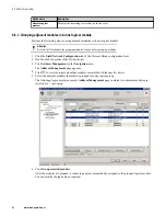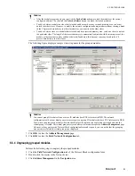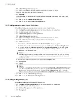
6.5 Adding a new GSD-based device to PROFIBUS Network Configuration
Tool library
A Generic Station Description (GSD) file is an electronic data description of a slave device. In accordance with
a standard format, the GSD file is a text file that is defined and supplied by the device vendor.
You can add new GSD-based devices to the “PROFIBUS Network Configuration Tool” library if they are not
available in the “PROFIBUS Network Configuration Tool”library.
Tip
You can obtain the GSD file from the device manufactures. You can also check for the GSD files in the PROFIBUS
website.
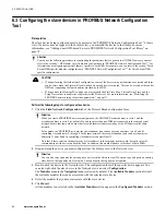
Perform the following steps to add a new GSD-based device to PROFIBUS Network Configuration Tool library
1
Copy the GSD file of the device into the following directory.
Documents and Settings\All Users
\Application Data\SYCONnet\PROFIBUS\GSD
.
For Windows 7, use the following directory.
C:\ProgramData\SYCONnet\PROFIBUS\GSD
.
Attention
You must copy only one version of the device GSD to the defined directory. If different versions (languages) are
copied, you will see the device as many times in the “PROFIBUS Network Configuration Tool” library. If the
same device exist several times in the “PROFIBUS Network Configuration Tool” library, the first one will be used
always irrespective of which one is dragged-and-dropped into the network view.
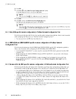
2
Click
Reload Catalog
on the
Field Network Configuration
tab toolbar to rebuild the device catalog. A
dialog box appears that displays the catalog update completion status.
The new device appears in the PROFIBUS Network Configuration Tool library after the catalog update is
complete.
Attention
If the device does not appear in the “PROFIBUS Network Configuration Tool” library, you must restart the
Control Builder.
6 PROTOCOL BLOCK
78
www.honeywell.com
Содержание Experion PKS
Страница 1: ...Experion PKS PROFIBUS Gateway Module User s Guide EPDOC XX88 en 431E June 2018 Release 431 ...
Страница 8: ...CONTENTS 8 www honeywell com ...
Страница 10: ...1 ABOUT THIS GUIDE 10 www honeywell com ...
Страница 32: ...4 PROFIBUS GATEWAY MODULE PGM INSTALLATION 32 www honeywell com ...
Страница 58: ...5 PROFIBUS GATEWAY MODULE PGM BLOCK 58 www honeywell com ...
Страница 69: ...6 PROTOCOL BLOCK 69 ...
Страница 103: ...5 Click OK 6 PROTOCOL BLOCK 103 ...
Страница 109: ...You can modify the following value from the Protocol Main tab detail display Alarming Enabled 6 PROTOCOL BLOCK 109 ...
Страница 110: ...6 PROTOCOL BLOCK 110 www honeywell com ...
Страница 181: ...7 20 3 Detail display tab Main tab Figure 4 Detail Display of Main tab 7 DEVICE SUPPORT BLOCK DSB 181 ...
Страница 182: ...Slave Status tab Figure 5 Detail Display of Slave Status tab 7 DEVICE SUPPORT BLOCK DSB 182 www honeywell com ...
Страница 183: ...PDC Details tab Figure 6 Detail Display of PDC Details tab 7 DEVICE SUPPORT BLOCK DSB 183 ...
Страница 184: ...DPV1 Details tab Figure 7 Detail Display of DPV1 Details tab 7 DEVICE SUPPORT BLOCK DSB 184 www honeywell com ...
Страница 185: ...Config Details tab Figure 8 Detail Display of Config Details tab 7 DEVICE SUPPORT BLOCK DSB 185 ...
Страница 186: ...7 DEVICE SUPPORT BLOCK DSB 186 www honeywell com ...
Страница 229: ...For a digital channel the detail display appears as follows 9 PROFIBUS I O MODULE PIOMB FUNCTION BLOCK 229 ...
Страница 231: ...9 PROFIBUS I O MODULE PIOMB FUNCTION BLOCK 231 ...
Страница 232: ...9 PROFIBUS I O MODULE PIOMB FUNCTION BLOCK 232 www honeywell com ...
Страница 236: ...10 PROFIBUS GATEWAY MODULE PGM CONFIGURATION EXAMPLE 236 www honeywell com ...
Страница 264: ...13 PROFIBUS GATEWAY MODULE PGM TROUBLESHOOTING 264 www honeywell com ...

