


• With R410, you can modify the values of the following parameters even after a PDC is associated and
connected to a PIOMB. However, you must ensure that you reload both the DSB and the PIOMB after
modifying the parameter value. If you do not reload both the DSB and the PIOMB, there may be a break in
the connection between the DSB and the PIOMB.
– Number of Channels (NUMCHANNEL) - You can increase or decrease the Number of Channels
parameter value. There is no restriction on increasing the number of channels. However, if you want to
decrease the number of channels, you can decrease the number only until the last assigned channel
number. For example, consider a scenario where you have entered the number of channels of a PDC as
10. However, you have assigned only 6 channels (channel 0 through channel 5) to the PROFIBUS
channels. In this scenario, you can reduce the Number of Channels value to 6. If you try to reduce the
Number of Channels value to 5 or less an error message appears.
– Channel Description (CHDESCRIPTION)
– Channel Type (CHANNELTYPE) - You can modify the Channel Type of a channel only if it that
particular channel is not associated with any PROFIBUS channel.
– Channel Data Type (CHANNELDATATYPE) - You can modify the Channel Data Type for both used
and unused channels. However, you must ensure that while modifying the channel data type for analog/
numeric channels, you must not select Boolean data type. Also, for digital channels you must only select
Boolean data type.
– Channel Low Range (CHLOWRANGE)
– Channel High Range (CHHIGHRANGE)
– Channel Data Offset (CHDATAOFFSET)
– Channel Bit Offset (CHBITOFFSET)
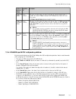
7.16.3 Generic DSB for PA devices (GENPADSB and GENPAGWDSB) specific PDC configuration
guidelines
The following list summarizes the GENPADSB and GENPAGWDSB specific PDC configuration guidelines
that you must remember while configuring the GENPADSB and GENPAGWDSB.
• The number of PDCs supported by GENPADSB is 8 and GENPAGWDSB is 64.
• In the
PA Status Usage
column, select the appropriate option to define how the data status is used by these
blocks. Based on the option selected in the
PA Status Usage
column, the channel status is updated in the
Status
column and the
PA Status
column.
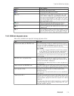
The following table summarizes the options that are available for the input/output channels and a brief
description of each option.
Options in
PA Status
Usage
column
Applicable
for
Description
Ignore
Both input
and output
channels
– For input channels, when you select this option, irrespective of the channel’s actual
state, the channel’s
Status
column always displays the status as
Good_NonCascade
and the
PA Status
column displays the value
Not Applicable
.
– For output channels, the channel status is always set to
GoodCasc_NonSpecific
.
However, the
PA Status
column displays the value
Not Applicable
.
Attention
If the PA device is removed from the network, the
PA Status
column displays the
value
Not Available
.
Update PA
status
Input
channels
When you select this option, the status is read from raw data. The channel’s
Status
column always displays the status as
Good_NonCascade
. However, the
PA Status
column displays the actual device status.
7 DEVICE SUPPORT BLOCK (DSB)
160
www.honeywell.com
Содержание Experion PKS
Страница 1: ...Experion PKS PROFIBUS Gateway Module User s Guide EPDOC XX88 en 431E June 2018 Release 431 ...
Страница 8: ...CONTENTS 8 www honeywell com ...
Страница 10: ...1 ABOUT THIS GUIDE 10 www honeywell com ...
Страница 32: ...4 PROFIBUS GATEWAY MODULE PGM INSTALLATION 32 www honeywell com ...
Страница 58: ...5 PROFIBUS GATEWAY MODULE PGM BLOCK 58 www honeywell com ...
Страница 69: ...6 PROTOCOL BLOCK 69 ...
Страница 103: ...5 Click OK 6 PROTOCOL BLOCK 103 ...
Страница 109: ...You can modify the following value from the Protocol Main tab detail display Alarming Enabled 6 PROTOCOL BLOCK 109 ...
Страница 110: ...6 PROTOCOL BLOCK 110 www honeywell com ...
Страница 181: ...7 20 3 Detail display tab Main tab Figure 4 Detail Display of Main tab 7 DEVICE SUPPORT BLOCK DSB 181 ...
Страница 182: ...Slave Status tab Figure 5 Detail Display of Slave Status tab 7 DEVICE SUPPORT BLOCK DSB 182 www honeywell com ...
Страница 183: ...PDC Details tab Figure 6 Detail Display of PDC Details tab 7 DEVICE SUPPORT BLOCK DSB 183 ...
Страница 184: ...DPV1 Details tab Figure 7 Detail Display of DPV1 Details tab 7 DEVICE SUPPORT BLOCK DSB 184 www honeywell com ...
Страница 185: ...Config Details tab Figure 8 Detail Display of Config Details tab 7 DEVICE SUPPORT BLOCK DSB 185 ...
Страница 186: ...7 DEVICE SUPPORT BLOCK DSB 186 www honeywell com ...
Страница 229: ...For a digital channel the detail display appears as follows 9 PROFIBUS I O MODULE PIOMB FUNCTION BLOCK 229 ...
Страница 231: ...9 PROFIBUS I O MODULE PIOMB FUNCTION BLOCK 231 ...
Страница 232: ...9 PROFIBUS I O MODULE PIOMB FUNCTION BLOCK 232 www honeywell com ...
Страница 236: ...10 PROFIBUS GATEWAY MODULE PGM CONFIGURATION EXAMPLE 236 www honeywell com ...
Страница 264: ...13 PROFIBUS GATEWAY MODULE PGM TROUBLESHOOTING 264 www honeywell com ...


