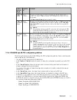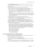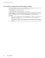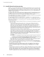
7.16.5 Siemens AS-I Link DSB specific PDC configuration guidelines
The following list summarizes the Siemens AS-I Link DSB specific PDC configuration guidelines that you
must remember while configuring the Siemens AS-I Link DSB PDC.
• The number of PDCs supported by the Siemens AS-I Link DSB is 16.
• The PDC types are mapped to the AS-i Slave devices.
• This DSB supports only the DI/DO channels.
• If you have configured a PDC with a net tag that maps to the data module on the second AS-i Segment,
select Segment 2 in the
ASISEGMENT
column.
– The AS-I segment column appears only while configuring the Siemens AS-i Link DSB for the AS-i Link
Advanced . This is because only AS-i Link Advanced supports two AS-I segments.
– The AS-i Segment (ASISEGMENT) parameter indicates the segment to which the PDC is configured.
This parameter can be used to identify whether the slave device is configured for Segment 1 or Segment
2. This parameter is applicable only to the Siemens AS-i Link DSB.
– It is an assumption that the configured data module for segment 2 must be in slot 2, and the configured
data module for segment 1 must be slot 1.
• The net tag associated with the PDCs types must map to the 4 bytes that covers the 7 or 8 slave devices
being referenced. For more information on the PDC types of the Siemens AS-I Link DSB, refer to the
PROFIBUS Gateway Module Parameter Reference Guide
.
• In the
Number of Channels
column, the number of channels are automatically updated based on the PDC
type. The "Slave 1-7 inputs" and "Slave 1-7 outputs" PDC types have 28 channels. The other PDC types
have 32 channels which are grouped as four channels for each slave device.
• In the
Channel Number
column, the channel number is automatically updated based on the number of
channels configured for the selected module.
For example, if the number of channels configured for a module is 4, then this column lists the channel
numbers as 0, 1, 2, and 3.
• In the
Channel Type
, the channel type is automatically selected based on the PDC type.
• In the
Channel Data Type
, the channel data type is always "Boolean" as this DSB supports only the DI and
DO channels.
• The
Channel Data Offset
column is not applicable to the Siemens AS-i Link DSB.
• The
Bit Offset
column is not applicable to the Siemens AS-i Link DSB.
• The
Low Range
column is not applicable to the Siemens AS-i Link DSB as this DSB does not support
analog channels.
• The
High Range
column is not applicable to the Siemens AS-i Link DSB as this DSB does not support
analog channels.
• With R410, you can modify the value of the following parameter even after a PDC is associated and
connected to a PIOMB. However, you must ensure that you reload both the DSB and the PIOMB after
modifying the parameter value. If you do not reload both the DSB and the PIOMB, there may be a break in
the connection between the DSB and the PIOMB.
– Channel Description (CHDESCRIPTION)
7.16.6 Siemens ET200M DSB specific PDC configuration guidelines
The following list summarizes the Siemens ET200M DSB specific PDC configuration guidelines that you must
remember while configuring the Siemens ET200M DSB PDC.
• The number of PDCs supported by the Siemens ET200M DSB is 16.
• The PDC configuration must be done through the
IOM configuration
tab.
• In the
Number of Channel
column, you must enter the number of channels manually.
7 DEVICE SUPPORT BLOCK (DSB)
162
www.honeywell.com
Содержание Experion PKS
Страница 1: ...Experion PKS PROFIBUS Gateway Module User s Guide EPDOC XX88 en 431E June 2018 Release 431 ...
Страница 8: ...CONTENTS 8 www honeywell com ...
Страница 10: ...1 ABOUT THIS GUIDE 10 www honeywell com ...
Страница 32: ...4 PROFIBUS GATEWAY MODULE PGM INSTALLATION 32 www honeywell com ...
Страница 58: ...5 PROFIBUS GATEWAY MODULE PGM BLOCK 58 www honeywell com ...
Страница 69: ...6 PROTOCOL BLOCK 69 ...
Страница 103: ...5 Click OK 6 PROTOCOL BLOCK 103 ...
Страница 109: ...You can modify the following value from the Protocol Main tab detail display Alarming Enabled 6 PROTOCOL BLOCK 109 ...
Страница 110: ...6 PROTOCOL BLOCK 110 www honeywell com ...
Страница 181: ...7 20 3 Detail display tab Main tab Figure 4 Detail Display of Main tab 7 DEVICE SUPPORT BLOCK DSB 181 ...
Страница 182: ...Slave Status tab Figure 5 Detail Display of Slave Status tab 7 DEVICE SUPPORT BLOCK DSB 182 www honeywell com ...
Страница 183: ...PDC Details tab Figure 6 Detail Display of PDC Details tab 7 DEVICE SUPPORT BLOCK DSB 183 ...
Страница 184: ...DPV1 Details tab Figure 7 Detail Display of DPV1 Details tab 7 DEVICE SUPPORT BLOCK DSB 184 www honeywell com ...
Страница 185: ...Config Details tab Figure 8 Detail Display of Config Details tab 7 DEVICE SUPPORT BLOCK DSB 185 ...
Страница 186: ...7 DEVICE SUPPORT BLOCK DSB 186 www honeywell com ...
Страница 229: ...For a digital channel the detail display appears as follows 9 PROFIBUS I O MODULE PIOMB FUNCTION BLOCK 229 ...
Страница 231: ...9 PROFIBUS I O MODULE PIOMB FUNCTION BLOCK 231 ...
Страница 232: ...9 PROFIBUS I O MODULE PIOMB FUNCTION BLOCK 232 www honeywell com ...
Страница 236: ...10 PROFIBUS GATEWAY MODULE PGM CONFIGURATION EXAMPLE 236 www honeywell com ...
Страница 264: ...13 PROFIBUS GATEWAY MODULE PGM TROUBLESHOOTING 264 www honeywell com ...


