


Attention
For PDCs that are configured as NI or NO module, CEAGDSB performs the following processing.
•
Updates the CHDATARAW parameter for INT32.
Channel Error Processing
The channel error status generated is delivered with the raw data. The error status bits are picked from the raw
data and used as the information while generating the channel status and channel alarms. The channel error is
transmitted only if the error reporting for the channel is allowed using the field network configuration.
Attention
The channel errors are transmitted for the analog values only if the range values are set to default (Low = 10000 and
High = 50000) in the field network configuration.
Extended Diagnostics
The extended diagnostics message contains the communication module diagnostic data and module status,
which are used for generating the CEAGDSB alarms. The additional module status information is used to
produce the channel status parameter of the PDC.
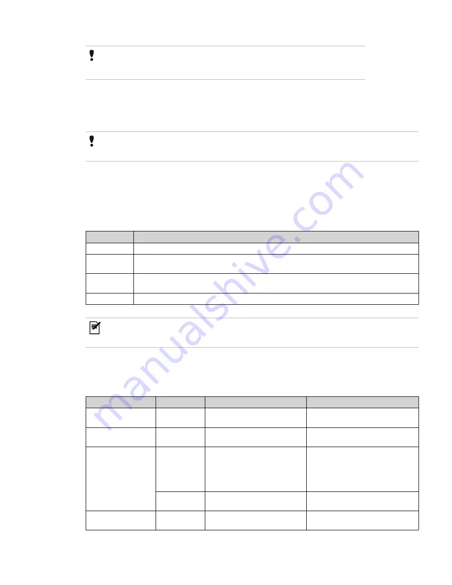
The following table lists the various module status values and a brief description of the state.
Module Status
Description
Data valid
This is the normal module status when there are no errors.
Module error
This state indicates that one or more channel error is active in the module. This state is applicable only to
the channels that are configured to allow channel error reporting in the Field Network Configuration.
Wrong module
This state indicates that the module type in the slot conflicts with the module type defined in Field
Network Configuration.
Missing module This state indicates that the module is physically not present in the configured slot.
Tip
You can view the diagnosis and extended diagnosis of the devices online. For more information, see “Viewing the
slave device diagnosis” on page 100 and “Viewing the slave device's extended diagnosis” on page 101 respectively.
Channel and module alarms based on module status and PDC type
The following table lists the behavior of the channel and module alarms, based on the module states and the
PDC types.
Module status
PDC type
Channel alarms
Module alarm
Missing module
IN/OUT
All channel alarms of module are
set to RETURNED to NORMAL.
Module alarm is set to ACTIVE,
parameter = missing module (4).
Wrong module
IN/OUT
All channel alarms of module are
set RETURNED to NORMAL.
Module alarm is set to ACTIVE,
parameter = wrong module (3).
Module error
IN
•
Alarms of channels reporting
error are set to ACTIVE.
•
Alarms of channels not
reporting error are set
RETURNED to NORMAL.
Module alarm is set to RETURNED to
NORMAL.
OUT
-
Module alarm is set ACTIVE,
parameter = module error (2).
Data valid
IN/OUT
All channel alarms of module are
set RETURNED TO NORMAL.
Module alarm is set RETURNED TO
NORMAL.
7 DEVICE SUPPORT BLOCK (DSB)
132
www.honeywell.com
Содержание Experion PKS
Страница 1: ...Experion PKS PROFIBUS Gateway Module User s Guide EPDOC XX88 en 431E June 2018 Release 431 ...
Страница 8: ...CONTENTS 8 www honeywell com ...
Страница 10: ...1 ABOUT THIS GUIDE 10 www honeywell com ...
Страница 32: ...4 PROFIBUS GATEWAY MODULE PGM INSTALLATION 32 www honeywell com ...
Страница 58: ...5 PROFIBUS GATEWAY MODULE PGM BLOCK 58 www honeywell com ...
Страница 69: ...6 PROTOCOL BLOCK 69 ...
Страница 103: ...5 Click OK 6 PROTOCOL BLOCK 103 ...
Страница 109: ...You can modify the following value from the Protocol Main tab detail display Alarming Enabled 6 PROTOCOL BLOCK 109 ...
Страница 110: ...6 PROTOCOL BLOCK 110 www honeywell com ...
Страница 181: ...7 20 3 Detail display tab Main tab Figure 4 Detail Display of Main tab 7 DEVICE SUPPORT BLOCK DSB 181 ...
Страница 182: ...Slave Status tab Figure 5 Detail Display of Slave Status tab 7 DEVICE SUPPORT BLOCK DSB 182 www honeywell com ...
Страница 183: ...PDC Details tab Figure 6 Detail Display of PDC Details tab 7 DEVICE SUPPORT BLOCK DSB 183 ...
Страница 184: ...DPV1 Details tab Figure 7 Detail Display of DPV1 Details tab 7 DEVICE SUPPORT BLOCK DSB 184 www honeywell com ...
Страница 185: ...Config Details tab Figure 8 Detail Display of Config Details tab 7 DEVICE SUPPORT BLOCK DSB 185 ...
Страница 186: ...7 DEVICE SUPPORT BLOCK DSB 186 www honeywell com ...
Страница 229: ...For a digital channel the detail display appears as follows 9 PROFIBUS I O MODULE PIOMB FUNCTION BLOCK 229 ...
Страница 231: ...9 PROFIBUS I O MODULE PIOMB FUNCTION BLOCK 231 ...
Страница 232: ...9 PROFIBUS I O MODULE PIOMB FUNCTION BLOCK 232 www honeywell com ...
Страница 236: ...10 PROFIBUS GATEWAY MODULE PGM CONFIGURATION EXAMPLE 236 www honeywell com ...
Страница 264: ...13 PROFIBUS GATEWAY MODULE PGM TROUBLESHOOTING 264 www honeywell com ...


