User-defined value
Description
0 - 100
•
For AO channels, numeric initialization value defines
percentage value of the output.
– If you define the initial value as 0, the AO channel
initializes to 0.
– If you define a nonzero value as the initialization value,
the AO channel initializes the output value using the
range defined by the low and the high range of the
channel.
Attention
If you want the output to be initialized to a low range,
you must enter a small non-zero value like 0.001 as
the initialization value. This enables the channel
value to initialize to the low range defined for the
channel. This difference is meaningful if an AO
channel is in 4-20 mA current loop.
•
For DO channels, initialization value 0 defines OFF state of
the channel and value 1 defines ON state of the channel.
NaN
If the initial value is defined as NaN, the output channels (AO
and DO) hold the last output value.
0
If the initial value is defined as 0, the AO channel initializes to
the low range defined for the channel and the DO channel is
cleared to 0 during all error scenarios.
Output channel behavior in various scenarios
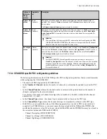
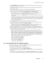
The following table summarizes the behavior of AO and DO channels in various scenarios in R410.2 and later
and R410.1 or earlier.
Scenario
Impact on AO/DO channel value in
Experion R410.2 and later
Impact on AO/DO channel value in
Experion R410.1 or earlier
DSB is loaded for the first time.
Clears to zero.
Clears to zero.
DSB is reloaded.
Drives values provided by the controller
for the connected PDCs.
Drives values provided by the controller
for the connected PDCs.
FTE connection break between
controller and PGM.
•
Holds the last value if the DSB is
configured to hold the last output
value.
•
If the DSB is not configured to hold
the last output value, channel values
are initialized from the user-defined
values.
•
Holds the last value if the DSB is
configured to hold the last output
value.
•
If the DSB is not configured to hold
the last output value, channel values
clear to zero.
Extended diagnostics report channel
failure.
Clears to zero.
Clears to zero.
Extended diagnostics report Module
failure.
Clears to zero.
Clears to zero.
An extended diagnostic overflow
condition exists but the DSB is not
configured to ignore extended
diagnostics overflow (the
Ignore
Extended Diagnostic Overflow
check box is not selected).
Clears to zero.
Clears to zero.
Standard diagnostics report
Station
Not Existent
error.
The channel values are initialized from
the user-defined values.
Clears to zero.
7 DEVICE SUPPORT BLOCK (DSB)
154
www.honeywell.com
Содержание Experion PKS
Страница 1: ...Experion PKS PROFIBUS Gateway Module User s Guide EPDOC XX88 en 431E June 2018 Release 431 ...
Страница 8: ...CONTENTS 8 www honeywell com ...
Страница 10: ...1 ABOUT THIS GUIDE 10 www honeywell com ...
Страница 32: ...4 PROFIBUS GATEWAY MODULE PGM INSTALLATION 32 www honeywell com ...
Страница 58: ...5 PROFIBUS GATEWAY MODULE PGM BLOCK 58 www honeywell com ...
Страница 69: ...6 PROTOCOL BLOCK 69 ...
Страница 103: ...5 Click OK 6 PROTOCOL BLOCK 103 ...
Страница 109: ...You can modify the following value from the Protocol Main tab detail display Alarming Enabled 6 PROTOCOL BLOCK 109 ...
Страница 110: ...6 PROTOCOL BLOCK 110 www honeywell com ...
Страница 181: ...7 20 3 Detail display tab Main tab Figure 4 Detail Display of Main tab 7 DEVICE SUPPORT BLOCK DSB 181 ...
Страница 182: ...Slave Status tab Figure 5 Detail Display of Slave Status tab 7 DEVICE SUPPORT BLOCK DSB 182 www honeywell com ...
Страница 183: ...PDC Details tab Figure 6 Detail Display of PDC Details tab 7 DEVICE SUPPORT BLOCK DSB 183 ...
Страница 184: ...DPV1 Details tab Figure 7 Detail Display of DPV1 Details tab 7 DEVICE SUPPORT BLOCK DSB 184 www honeywell com ...
Страница 185: ...Config Details tab Figure 8 Detail Display of Config Details tab 7 DEVICE SUPPORT BLOCK DSB 185 ...
Страница 186: ...7 DEVICE SUPPORT BLOCK DSB 186 www honeywell com ...
Страница 229: ...For a digital channel the detail display appears as follows 9 PROFIBUS I O MODULE PIOMB FUNCTION BLOCK 229 ...
Страница 231: ...9 PROFIBUS I O MODULE PIOMB FUNCTION BLOCK 231 ...
Страница 232: ...9 PROFIBUS I O MODULE PIOMB FUNCTION BLOCK 232 www honeywell com ...
Страница 236: ...10 PROFIBUS GATEWAY MODULE PGM CONFIGURATION EXAMPLE 236 www honeywell com ...
Страница 264: ...13 PROFIBUS GATEWAY MODULE PGM TROUBLESHOOTING 264 www honeywell com ...


