


9
In the
User Condition Channel
column, enter the channel number of the PDC selected that you want to set
the status based on the alarm condition. This parameter defines whether one/all channels of PDC configured
in the USERCONDITPDC parameter is affected when configured alarm is active. The possible values of
this parameter are as follows:
• 255 - This means all channels of configured PDC will be affected when configured alarm is active.
• 0 ..MAXNUMOFCHANELS - When this parameter is configured in the range
0..MAXNUMOFCHANELS, then only the configured channel will be affected when configured alarm is
active.
10
In the
Alarm Priority
column, select the alarm priority as required.
• For GENDSB, the first 8 alarms have the default value as “HIGH” and remaining 24 alarms have the
default value as “LOW.”
• For GENIODSB, the default value is “NONE.”
11
In the
Alarm Severity
column, enter the alarm severity as required. The default value of this parameter is 0
for both GENDSB and GENIODSB.
12
In the
Enable RIO Profile
check box, select this check box if you want the DSB to process the RIO
diagnostics for devices that conform to RIO standards.
The
Enable RIO Profile
check box is applicable only for GENDSB and GENIODSB.
13
In the
Ignore Extended Diagnostic Overflow
check box, select this check box if you want to ignore the
extended diagnostic overflow condition and perform normal processing of diagnostic received.
• The
Ignore Extended Diagnostic Overflow
check box is applicable only for GENDSB and
GENIODSB.
• The
Ignore Extended Diagnostic Overflow
check box is enabled only when the
Enable RIO Profile
check box is enabled.
• If you do not select the
Ignore Extended Diagnostic Overflow
check box, all channels of all PDCs are
set to “Bad_NonSpecific” if the diagnostic overflow condition exists.
Attention
When an extended diagnostic overflow condition exists, all the channels of all the PDC’s are set to
Bad_NonSpecific. This is applicable to all DSBs.
14
Select the
Enable PA Profile Diagnostics
check box or the
Enable GW Diagnostics
check box if you want
to enable the PA profile-based alarming or the IM-157 diagnostics based alarming respectively.
• By default, this option is disabled.
• For GENPADSB, this check box appears as
Enable PA Profile Diagnostics
.
For GENPAGWDSB, this check box appears as
Enable GW Diagnostics
.
15
Select the first acceptable PA status value in the
First Acceptable PA Status Value
list for the channel such
that an alarm is reported if the channel status is below this defined value.
Attention
•
The
First Acceptable PA Status Value
check box is applicable only for the GENPADSB and
GENPAGWDSB.
•
This alarm is reported only if you have selected the option
Update Ch status and alarm
in the
PA Status
Usage
column while configuring the PDC.
•
The
First acceptable PA Status Value
list provides the list of all possible PA status values. By default, the
value is set to
Good_NonCascade
.
16
Click
OK
.
7 DEVICE SUPPORT BLOCK (DSB)
170
www.honeywell.com
Содержание Experion PKS
Страница 1: ...Experion PKS PROFIBUS Gateway Module User s Guide EPDOC XX88 en 431E June 2018 Release 431 ...
Страница 8: ...CONTENTS 8 www honeywell com ...
Страница 10: ...1 ABOUT THIS GUIDE 10 www honeywell com ...
Страница 32: ...4 PROFIBUS GATEWAY MODULE PGM INSTALLATION 32 www honeywell com ...
Страница 58: ...5 PROFIBUS GATEWAY MODULE PGM BLOCK 58 www honeywell com ...
Страница 69: ...6 PROTOCOL BLOCK 69 ...
Страница 103: ...5 Click OK 6 PROTOCOL BLOCK 103 ...
Страница 109: ...You can modify the following value from the Protocol Main tab detail display Alarming Enabled 6 PROTOCOL BLOCK 109 ...
Страница 110: ...6 PROTOCOL BLOCK 110 www honeywell com ...
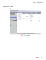
Страница 181: ...7 20 3 Detail display tab Main tab Figure 4 Detail Display of Main tab 7 DEVICE SUPPORT BLOCK DSB 181 ...
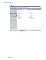
Страница 182: ...Slave Status tab Figure 5 Detail Display of Slave Status tab 7 DEVICE SUPPORT BLOCK DSB 182 www honeywell com ...
Страница 183: ...PDC Details tab Figure 6 Detail Display of PDC Details tab 7 DEVICE SUPPORT BLOCK DSB 183 ...
Страница 184: ...DPV1 Details tab Figure 7 Detail Display of DPV1 Details tab 7 DEVICE SUPPORT BLOCK DSB 184 www honeywell com ...
Страница 185: ...Config Details tab Figure 8 Detail Display of Config Details tab 7 DEVICE SUPPORT BLOCK DSB 185 ...
Страница 186: ...7 DEVICE SUPPORT BLOCK DSB 186 www honeywell com ...
Страница 229: ...For a digital channel the detail display appears as follows 9 PROFIBUS I O MODULE PIOMB FUNCTION BLOCK 229 ...
Страница 231: ...9 PROFIBUS I O MODULE PIOMB FUNCTION BLOCK 231 ...
Страница 232: ...9 PROFIBUS I O MODULE PIOMB FUNCTION BLOCK 232 www honeywell com ...
Страница 236: ...10 PROFIBUS GATEWAY MODULE PGM CONFIGURATION EXAMPLE 236 www honeywell com ...
Страница 264: ...13 PROFIBUS GATEWAY MODULE PGM TROUBLESHOOTING 264 www honeywell com ...


