Hitachi RAS-(2-6)HVNP1(E) Скачать руководство пользователя страница 167

5 Control System

153

SMGB0087 rev.0 - 12/2013

5







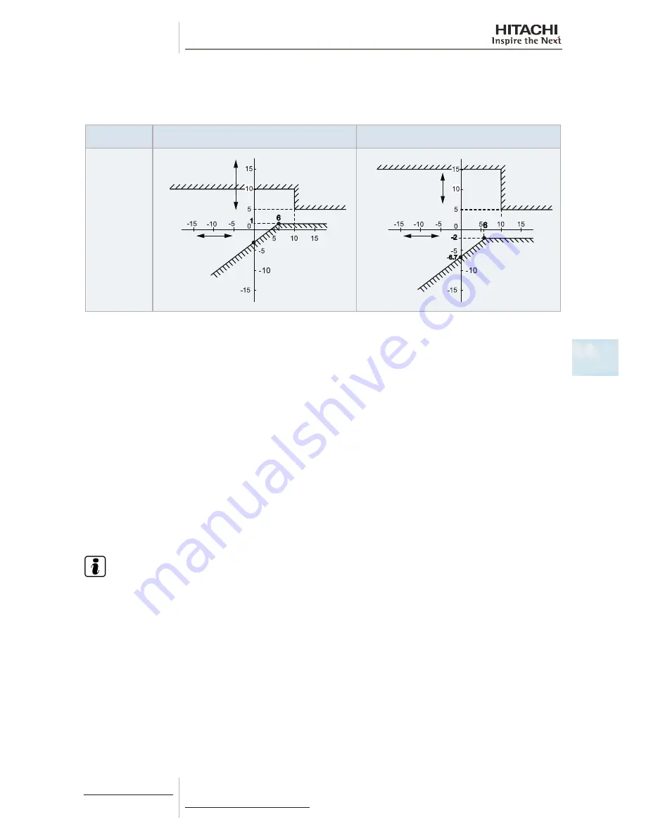
Condition for Starting Defrost

Standard defrost

a. 

Temperature condition

Model

RAS-(2-2.5)HVNP1 

RAS-3HVNC1

RAS-3HVNP1E 

RAS-(4-12)H(V)N(P/C)(1)(E)

Temperature 

condition under 

defosting  

operation

-4.6

Defrosting 

operation 

start area

Defrosting 

operation 

stop area

Outdoor 

temperature 

(ºC)

Outdoor evaporating 

temperature (ºC) 

(pipe)

Defrosting 

operation 

start area

Defrosting 

operation 

stop area

Outdoor 

temperature 

(ºC)

Outdoor evaporating 

temperature (ºC) 

(pipe)

b. 

Condition for Operating Time of Defrost Operation Start

The defrosting operation is started when the temperature condition is met “(a) Temperature Condition” after the heating 
operation is performed for 40 to 120 minutes.  The heating operation time is determined by estimating the amount of fros-
ting on the heat exchanger.

Forced Defrost

Condition for Starting
The forced defrosting operation is started when all the following conditions are met.

a. 

120 minutes are passed after the reversing valve is “ON”.

b. 

The outdoor temperature is lower than 10ºC.

c. 

The accumulated heating operation time is more than 60 minutes. (*1) 
(The accumulated time is reset when the operation is stopped or the defrosting operation is performed.)

d. 

The compressor is operated continuously for more than 1 and half minutes. (*2)

e. 

The outdoor evaporating temperature is lower than 5ºC (*3) right before starting the operation. 

f. 

The pressure switch for control is “OFF”.

  N O T E

For RAS-(2-2.5)HVNP1 / RAS-3HVNC1:
•  (*1) More than 39 minutes.
•  (*2) If outdoor temperature is less than -6ºC then the compressor is operated continuously for more than 2 minutes. If 

outdoor temperature is more than -6ºC then the compressor is operated continuously for more than 9 minutes.

•  (*3) Less than 6ºC.

Содержание RAS-(2-6)HVNP1(E)

Страница 1: ...Service Manual UTOPIA IVX PREMIUM IVX STANDARD SERIES H V N P C 1 E RAS 2 6 HVNP1 E RAS 4 12 HNP 1 E RAS 3 6 HVNC1 E RAS 4 12 HNC 1 E ...

Страница 2: ......

Страница 3: ...l information Unit Installation Piping work and refrigerant charge Electrical wiring Control System Optional functions Test run Troubleshooting Spare parts Servicing Electrical checks of main parts Maintenance notes 1 2 3 4 5 6 7 8 9 10 11 12 ...

Страница 4: ... II ...

Страница 5: ... summary 16 2 2 Transportation of outdoor unit 17 2 3 Center of gravity 18 2 4 Factory supplied accessories for RAS 12HN P C 19 2 5 Installation space Initial ckeck 20 2 5 1 Basic sizes 20 2 5 2 RAS 2 2 5 HVNP1 RAS 3HVNC1 21 2 5 3 RAS 3 12 H V NP 1 E RAS 3HVNC1 RAS 12HNC 22 2 5 4 RAS 4 6 H V NC1E 25 2 6 Place provision 27 2 6 1 Place provision for RAS 2 2 5 HVNP1 RAS 3HVNC1 27 2 6 2 Place provisio...

Страница 6: ...on 77 3 3 6 System installation 80 3 3 7 Connecting flare adapter 82 3 4 Refrigerant charge 83 3 4 1 Caution of the pressure by check joint 84 3 4 2 Refrigerant charge quantity 84 3 5 Caution in case of refrigerant leakage 89 3 5 1 Maximum permitted concentration of hydrofluorocarbon HFC 89 3 5 2 Calculation of refrigerant concentration 89 3 5 3 Countermeasure for refrigerant leakage 89 3 6 Compat...

Страница 7: ...taneous Operation 117 4 7 Electrical wiring diagrams 118 4 7 1 RAS 2 2 5 HVNP1 RAS 3HVNC1 1 230V 50Hz 118 4 7 3 RAS 3HVNP1E 1 230V 50Hz 120 4 7 4 RAS 4 6 HVNP1E 1 230V 50Hz 122 4 7 6 RAS 4 6 HNP1E 3N 400V 50Hz 124 4 7 7 RAS 4 6 HVNC1E 1 230V 50Hz 126 4 7 8 RAS 4 6 HNC1E 3N 400V 50Hz 128 4 7 10 RAS 8 10 HN P C E 3N 400V 50Hz 130 4 7 12 RAS 12HN P C 3N 400V 50Hz 132 5 Control System 135 5 1 Device c...

Страница 8: ...al signals 168 6 2 Optional functions By 7 segment display 171 6 2 1 Setting of the optional functions 171 6 2 2 Description of the optional functions 175 6 3 Optional functions By remote control switch 182 7 Test run 191 7 1 Checking procedure before the test run 192 7 2 Test run procedure using the remote control switch PC ART 194 7 3 Test run procedure using the remote control switch PC ARF 196...

Страница 9: ...he capacitors CB1 CB2 309 8 4 4 Checking procedeure for the DC fan motor 310 8 4 5 Checking procedure for the AC fan motor 311 8 4 6 Checking procedure for the electronic expansion valve for indoor and outdoor units 311 8 4 7 Checking procedure for other parts 312 9 Spare parts 319 9 1 RAS 2 2 5 HVNP1 320 9 1 1 Cycle and structural parts 320 9 1 2 Parts table 321 9 2 RAS 3HVNC1 322 9 2 1 Cycle and...

Страница 10: ...oving upper cover 362 10 3 4 Removing bottom service cover and rear cover 362 10 3 5 Removing outdoor fan motor 363 10 3 6 Removing electrical box 364 10 3 7 Removing the compressor 365 10 3 8 Removing the High pressure switch and Pressure switch for control 367 10 3 9 Opening electrical box P plate 368 10 3 10 Removing Reversing valve coil 368 10 3 11 Removing electronic expansion valve coil 368 ...

Страница 11: ...itch for control 391 10 5 9 Opening electrical box P Mounting Plate 391 10 5 10 Removing reversing valve coil 392 10 5 11 Removing electronic expansion valve coil 392 10 5 12 Removing solenoid valve coil SVA and SVC 393 10 5 13 Removing reversing valve 393 10 5 14 Removing Electronic expansion Valve and Solenoid Valve 394 10 5 15 Removing electrical components 395 10 5 16 Removing other electrical...

Страница 12: ...er electrical components 425 10 8 RAS 8 10 HNCE 426 10 8 1 Removing service cover 426 10 8 2 Removing air outlet grille 426 10 8 3 Removing upper cover 427 10 8 4 Removing the bottom service cover and rear cover 427 10 8 5 Removing outdoor fan motor 428 10 8 6 Removing electrical box 429 10 8 7 Removing the compressor 430 10 8 8 Removing High pressure switch and pressure switch for control 433 10 ...

Страница 13: ... 458 11 2 Thermistor 459 11 3 Electronic expansion valve 462 11 4 High pressure protection device 463 11 5 Noise filter NF 465 11 5 1 Noise filter for 3N 400V 50Hz 465 11 5 2 Noise filter for 1 230V 50Hz 466 11 6 Capacitor CB1 CB2 8 10 12 HP only 467 11 7 Reactor DCL 468 11 7 1 Reactor DCL for 3N 400V 50Hz 468 11 7 2 Reactor DCL for 1 230V 50Hz 468 11 8 Scroll compressor 469 11 8 1 Reliable mechan...

Страница 14: ...Maintenance work 475 12 3 Service and maintenance record 476 12 4 Service and maintenance record using the 7 segment display 477 12 5 Service and maintenance record by remote control switch 479 12 6 Pump down method for replacing the compressor 480 ...

Страница 15: ...4 1 2 2 Norms and Regulations 4 1 3 Product guide 5 1 3 1 Classification of outdoor unit models 5 1 3 2 Classification of indoor unit models 5 1 3 3 Product guide Outdoor units 6 1 3 4 Outdoor unit accessory code list 7 1 3 5 Product guide Indoor units complementary systems 9 1 3 6 Product line up KPI energy heat recovery unit 12 1 3 7 Product line up DX Interface 13 1 G ener al i nfor mation ...

Страница 16: ...ame IVX outdoor unit depending on model New UTOPIA series consists in two different outdoor unit series IVX Premium and IVX Standard which compliant with the Seasonal Efficiency driven by the EU s Energy Product Directive Eco Design Directive EuP Lot 10 and Seasonal Efficiency design concept in order to meet the European Directive on seasonal efficiency Lot 6 21 coming in 2015 depen ding on the mo...

Страница 17: ...turing and installation process to reflect HITACHI s awareness of environmental respect and commitment R410A is totally environmentally friendly since it does not contain any substances that damage the ozone layer ODP ozone depleting product 0 HITACHI s UTOPIA series are very efficient and allow significant energy savings compared with conventional systems This energy efficiency means less product...

Страница 18: ...ies of the unit In the texts following the danger symbol you can also find information on safe procedures during unit installation C A UTION The text following this symbol contains information and instructions relating directly to your safety and physical well being Not taking these instructions into account could lead to minor injuries to you and others in the proximities of the unit Not taking t...

Страница 19: ...ries C Standard series series 0 1 series 1 E Made in Europe Made in Japan RAS XX H X N X X X 1 3 2 Classification of indoor unit models Unit type indoor unit RCI RCIM RCD RPC RPI RPIM RPK RPF RPFI Position separating hyphen fixed Capacity HP 0 8 1 0 1 5 2 0 2 5 3 0 4 0 5 0 6 0 8 0 10 0 FS SYSTEM FREE N R410A refrigerant H Hotel RPK 0 8 1 5 only 2 3 4 series E Made in Europe M Made in Malaysia Made...

Страница 20: ...020 RAS 4HNP1E 7E304120 RAS 5HVNP1E 7E304021 RAS 5HNP1E 7E304121 RAS 6HVNP1E 7E304022 RAS 6HNP1E 7E304122 RAS 8HNPE 7E310110 RAS 10HNPE 7E310111 RAS 12HNP 6028863 IVX Standard 1 230V 50Hz 3N 400V 50Hz Unit Code Unit Code Unit Code Unit Code Unit Code RAS 3HVNC1 6028867 RAS 4HVNC1E 7E305034 RAS 4HNC1E 7E305134 RAS 5HVNC1E 7E305035 RAS 5HNC1E 7E305135 RAS 6HVNC1E 7E305036 RAS 6HNC1E 7E305136 RAS 8HN...

Страница 21: ...HVNP1 RAS 3HVNC1 b RAS 3HVNP1E c RAS 4 6 HVNC1E d RAS 4 6 H V NPE RAS 8 10 HN P C E f RAS 12HN P C g Name OU Ref Description Code Figure DBS 26 a Drain discharge connection 60299192 AG 264 b Air flow guide 60209100 AG 335A d c f g Air flow guide 60291431 WSP 264 b Wind guard 60291831 WSP 335A d c f g Wind guard 60291432 ...

Страница 22: ...te 60291778 ASG NP335B g Snow protection hood air inlet of rear side Zinc plate 60291434 ASG NP335BS2 g Snow protection hood air inlet of rear side Stainless plate ASG SP10BE d Snow protection hood air inlet of rear side Steel plate ASG SP10BES d Snow protection hood air inlet of rear side Stainless plate ASG NP56L b Snow protection hood air inlet of left side Zinc plate ASG NP63LS2 b Snow protect...

Страница 23: ...60278121 RCIM 1 5FSN3 60278174 RCI 2 5FSN3Ei 7E403017 RCI 2 5FSN3Ek 7E404004 RCI 2 5FSN3 60278122 RCIM 2 0FSN3 60278175 RCI 3 0FSN3Ei 7E403018 RCI 3 0FSN3Ek 7E404005 RCI 3 0FSN3 60278123 RCI 4 0FSN3Ei 7E403020 RCI 4 0FSN3Ek 7E404007 RCI 4 0FSN3 60278124 RCI 5 0FSN3Ei 7E403021 RCI 5 0FSN3Ek 7E404008 RCI 5 0FSN3 60278125 RCI 6 0FSN3Ei 7E403022 RCI 6 0FSN3Ek 7E404009 RCI 6 0FSN3 60278126 Panels Optio...

Страница 24: ...165 RCD 2 5FSN2 60278032 RPC 2 5FSN3E 7E443004 RPC 2 5FSN3 60278166 RCD 3 0FSN2 60278033 RPC 3 0FSN3E 7E443005 RPC 3 0FSN3 60278167 RCD 4 0FSN2 60278034 RPC 4 0FSN3E 7E443007 RPC 4 0FSN3 60278168 RCD 5 0FSN2 60278035 RPC 5 0FSN3E 7E443008 RPC 5 0FSN3 60278169 RPC 6 0FSN3E 7E443009 RPC 6 0FSN3 60278170 Panels Optional P N23DNA 60297211 P N46DNA 60297212 N OTE The RCD models must be used in combinat...

Страница 25: ...7E424013 RPIM 0 8FSN4E 7E430013 RPIM 0 8FSN4E DU 7E431013 RPI 1 0FSN4E 7E424014 RPIM 1 0FSN4E 7E430014 RPIM 1 0FSN4E DU 7E431014 RPI 1 5FSN4E 7E424015 RPIM 1 5FSN4E 7E430015 RPIM 1 5FSN4E DU 7E431015 RPI 2 0FSN4E 7E424016 RPI 2 5FSN4E 7E424017 RPI 3 0FSN4E 7E424018 RPI 4 0FSN4E 7E424020 RPI 5 0FSN4E 7E424021 RPI 6 0FSN4E 7E424022 RPI 8 0FSN3E 7E424010 RPI 10 0FSN3E 7E424011 ...

Страница 26: ...004 RPFI 2 5FSN2E 7E460004 RPK 2 5FSN3M 60278150 RPK 3 0FSN3M 60278151 RPK 4 0FSN3M 60278152 Expansion valve kit 1 EV 1 5N1 1 60291791 NO TE Single combinations with IVX Premium Standard series not allowed 1 For RPK 0 8 1 5 FSNH3M models only 1 3 6 Product line up KPI energy heat recovery unit Complementary systems KPI Energy recovery Heat recovery Active Energy Recovery DX section Unit Code Unit ...

Страница 27: ...13 1 1 3 7 Product line up DX Interface DX Interface Control box Expansion valve box Unit Code EXV 2 0E1 7E610900 EXV 2 5E1 7E610901 EXV 3 0E1 7E610902 EXV 4 0E1 7E610903 EXV 5 0E1 7E610904 EXV 6 0E1 7E610905 EXV 8 0E1 7E610906 EXV 10 0E1 7E610907 ...

Страница 28: ......

Страница 29: ...V NC1E 25 2 6 Place provision 27 2 6 1 Place provision for RAS 2 2 5 HVNP1 RAS 3HVNC1 27 2 6 2 Place provision for RAS 3HVNP1E RAS 4 6 H V N P C 1E RAS 8 10 HN P C E RAS 12HN P C 29 2 7 Optional parts and installation 32 2 7 1 Optional parts and installation for RAS 2 2 5 HVNP1 RAS 3HVNC1 32 2 7 2 Optional parts and installation RAS 3HVNP1E 37 2 7 3 Optional parts and installation RAS 4 6 H V NC1E...

Страница 30: ... area not accessible by the general public Aluminium fins have very sharp edges Pay attention to the fins in order to avoid injury Do not install the indoor units in a flammable environment to avoid a fire or an explosion Check to ensure that the ceiling slab is strong enough If not strong enough the indoor unit may fall down on you Do not install the indoor units outdoor unit remote control switc...

Страница 31: ... H V NC1E RAS 12HN P C 1 A B C D 1 A B C D 1 Wire rope A Over 60º B 0 7 to 1 0 m C Do not remove the plastic band or the corrugate paper frame D Pass the wire ropes through each lifting hole in the wooden base as shown CAUTION Lift the outdoor unit in its factory packaging with 2 wire ropes For safety reasons ensure that the outdoor unit is lifted smoothly and does not lean Do not attach lifting e...

Страница 32: ...condition with two ropes as shown below At leat two persons are needed to move the unit RAS 2 2 5 HVNP1 RAS 3HVNC1 a 515 mm b 180 mm h 275 mm 1 RAS 3HVNP1E a 600 mm b 195 mm h 370 mm 1 RAS 4 6 H V NC1E For 4 HP a 590 mm b 195 mm h 510 mm For 5 6 HP a 610 mm b 195 mm h 490 mm RAS 4 6 H V NP1E a 613 mm b 190 mm h 590 mm RAS 8HNPE a 610 mm b 195 mm h 570 mm RAS 8HNCE a 615 mm b 190 mm h 560 mm RAS 10...

Страница 33: ...uantity 2 0 4 0 Product Fiche 1 Declaration of conformity 1 Energy Label 1 Transportation Label 1 Installation and operation manual 1 5 0 10 0 Declaration of conformity 1 Transportation Label 1 Installation and operation manual 1 12 Declaration of conformity 1 Transport Label 1 Instalation and operation manual 1 Pipe with flare nut for refrigerant piping 1 NO TE If any of these accessories are not...

Страница 34: ... NO TE The following images are for illustration purposes only 2 5 1 Basic sizes RAS 2HVNP1 RAS 2 5HVNP1 RAS 3HVNC1 50 200 250 100 100 200 RAS 4 6 H V NC1E All models except RAS 2HVNP1 RAS 2 5HVNP1 RAS 3HVNC1 RAS 4 6 H V NC1E Units in mm 600 200 50 200 600 100 50 600 200 300 600 100 ...

Страница 35: ... H A 1000 d In case that upper side obstacles exist serial units e In case of front side and either of the sides are open serial units 200 300 0 L 1 2 H A 500 1 2 H L H A 1000 300 f In case that surrounding wall exist serial units 0 L 1 2 A 500 1 2 H L H A 1000 A L 1000 0 L 1 2 H A 200 1 2 H L H A 350 g Horizontal multiple units h Vertical multiple units 0 L 1 2 H A 100 1 2 H L H A 200 1000 400 20...

Страница 36: ...es Be sure to use the fan direction guide Allow 100 mm of space between units Leave open both right and left sides Upper Side Blocked Single Installation Multiple Installation Two units or more 100 mm or more of the side space is acceptable on the service cover side Allow 100 mm of space between units Leave open both right and left sides Leave open both right and left sides Be sure to use the fan ...

Страница 37: ...open both right and left sides Be sure to use the fan direction guide Allow 100 mm of space between units Leave open both right and left sides No more than 2 units for multiple installation The length A is as shown in the following table L A 0 L 1 2H 600 or greater 1 2H L H 1400 or greater When L H use a base for outdoor unit to make L H Close the base not to allow the outlet air bypassed Lateral ...

Страница 38: ... part A not to allow the outlet air bypassed Install to avoid the drain water from upper unit falling on the lower unit Be sure to use the fan direction guide Allow 100 mm of space between units Serial side way installation allowed but leave open both right and left sides Close the part A not to allow the outlet air bypassed Install to avoid the drain water from upper unit falling on the lower uni...

Страница 39: ...locked in Inlet Side Upper Side Open Single Installation Multiple Installation Two units or more Front Side Upper Side Blocked Single Installation Multiple Installation Two units or more Outlet Side Blocked Upper Side Open Single Installation Multiple Installation Two units or more ...

Страница 40: ...ions Mount the airflow guide and provide sufficient space on both right and left sides When using airflow guide AG 335A op tional check that the discharged air is not short circuited to the air inlet side A B 0 L 1 2H 1 2H L H 0 L 1 2H 1 2H L H Min 600 Min 1400 Min 300 Min 350 When L H use a base for outdoor unit to make L H Close the base not to allow the outlet air bypassed ...

Страница 41: ... 6 1 Place provision for RAS 2 2 5 HVNP1 RAS 3HVNC1 1 Secure the outdoor unit with the anchor 1 Base of outdoor unit 2 Nut 3 Special washer M12 4 Anchor bolts 5 Filled mortar 6 Concrete A Max 17 mm 1 2 3 4 5 6 A Fix the outdoor unit to the anchor bolts by special washer of factory supplied accessory 2 When installing the outdoor unit fix the unit by anchor bolts Regarding the location of fixing ho...

Страница 42: ...0 mm Frame width Field supplied C 100 mm or more Metal plate INCORRECT CORRECT Recommended Metal Plate Size Field Supplied Material Hot Rolled Mild Steel Plate SPHC Plate Thickness 4 5 T 120 60 560 70 420 70 20 14 R 4 C10 320 460 Installing location where the unit will be exposed to strong wind Follow the instructions below to install on the rooftop or a location without surrounding buildings wher...

Страница 43: ...ard piping space 1 2 3 4 5 6 7 4 Anchor bolt location in case of RAS 12HN P C 1 The whole base of the outdoor unit should be installed on a foundation When using vibration proof material it should also be positioned in the same place When installing the outdoor unit on a field supplied frame use metal plates to adjust the frame width for stable installation as shown in the figure below 1 Outdoor u...

Страница 44: ...this type of anchor bolt is used If not done it will be dificult to remove the ser vice cover B 1 2 3 Fix unit to the wall 1 Fix the unit onto the wall as shown in the figures Field supplied bracket 2 Secure the foundation to avoid noise and warping 3 To avoid vibrations transferring to the building use a rubber mat RAS 3HVNP1E RAS 4 6 H V NC1E RAS 4 6 H V NP1E RAS 8 10 HN P C E RAS 12HN P C A 1 2...

Страница 45: ...that the installation is sturdy enough to prevent falls Secure the unit with cables field supplied when installing the unit in a place without walls or wind protection and where it is likely to be exposed to gusts of wind When using the vibration proof rubber mat secure it at four points on the front and back Installing location where the unit will be exposed to strong wind Follow the instructions...

Страница 46: ... 1 2 1 Mounting dimension 2 Air flow guide Air discharge direction Upward downward left right Material Weather proof polypropylene resin Color Gray Weight 1 4 kg Accessories Fixing screw 4x M5 SUS x 12 4x M5 SUS x 30 Installation manual Self screw 2x M4 x 13 Installation restriction Wind Guard or Snow protection hood is not available to install with air flow guide Guard net is available to be inst...

Страница 47: ...ille 2 Air flow 3 Outdoor unit 4 M5 fixing screw x4 Accessories 5 Air flow guide 1 2 3 4 4 5 Service space In case of upward air discharge In case of right and left sides air discharge enough space for air discharge is required The downward air discharge is also available In such case install the base under the unit to secure enough space for air discharge In case of serial units installation air ...

Страница 48: ...rd Attaching example of air wind guard Attach the air flow guide to the air discharge grille with four 4 screws supplied The fixing holes are located at 4 positions on the grille Screw tightening torque 2 4 3 1 N m Do not remove the air discharge grille for air flow guide installation C A UTI ON If the air guide is installed without discharge grille it may cause injury due to rotating fan Two wind...

Страница 49: ...for safety wire rope to prevent overturning Rear suction hood Nº Part name Quantity 1 Right side plate 1 2 Left side plate 1 3 Upper front panel Upside 1 4 Upper front panel Downside 1 5 Hole for safety wire rope to prevent overturning 6 Fixing screw Accessories Left suction hood Nº Part name Quantity 1 Right side plate 1 2 Left side plate 1 3 Upper front panel Upside 1 4 Upper front panel Downsid...

Страница 50: ...sheet Iron Stainless NSSC180 Bonderized steel sheet Iron Stainless NSSC180 Bonderized steel sheet Iron Stainless NSSC180 Color Gray 1 0Y8 5 0 5 or approximation Gray 1 0Y8 5 0 5 or approximation Gray 1 0Y8 5 0 5 or approximation Weight 3 kg 6 kg 3 kg Assembling Knockingdown parts assembled at field Components Hood For air discharge part x 1 For rear side air intake x 1 For left side air intake x 1...

Страница 51: ...it 1 1 2 1 Mounting dimension 2 Air flow guide Air discharge direction Upward downward left right Material Weather proof polypropylene resin Color Gray Weight 1 9 kg Accessories Fixing screw x 4 M5 SUS x 20 Installation manual Installation restriction Wind Guard or Snow protection hood is not available to install with air flow guide Guard net is available to be installed together Attaching example...

Страница 52: ... install the base under the unit to secure enough space for air discharge In case of serial units installation air discharge should be upward 1 Min 200 mm 2 Outdoor unit 3 Air flow guide 4 Passage side Wind guard Specifications Model WSP 335A Quantity 1 per unit 1 1 2 2 3 1 Mounting dimension 2 Air flow 3 3 4xØ7 Material Galvanized sheet metal baked painting Color Gray 1 0Y8 5 0 5 Weight 5 5 kg Ac...

Страница 53: ...e the air discharge grille for air flow guide installation CAUTION If the air guide is installed without discharge grille it may cause injury due to rotating fan One windguard cover installation 1 Air discharge grille 2 Wind guard 3 Air discharge grille 4 Outdoor unit 5 M5 fixing screw x4 Accessories 1 2 3 4 5 Service space Both sides of the outdoor unit should be open No obstacles should be place...

Страница 54: ...t overturning Rear suction hood Nº Part name Quantity 1 Right side plate 1 2 Left side plate 1 3 Upper front panel Upside 1 4 Upper front panel Downside 1 5 Fixing screw Accessories 6 Hole for safety wire rope to prevent overturning Left suction hood Nº Part name Quantity 1 Right side plate 1 2 Left side plate 1 3 Front panel Upside 1 4 Front panel Downside 1 5 Fixing hole x 2 6 Fixing screw Acces...

Страница 55: ...nless NSSC 180 Bonderized steel sheet Iron Stainless NSSC 180 Color Gray 1 0Y8 5 0 5 or approximation Gray 1 0Y8 5 0 5 or approximation Gray 1 0Y8 5 0 5 or approximation Weight 3 kg 14 kg 8 kg Assembling Knockingdown parts assembled at field Components Hood For air discharge part x 1 For rear side air intake x 1 Upper side x 1 lowe side x 1 For left side air intake x 1 Unit Fixing screw 4 M5x12 ta...

Страница 56: ... unit 1 1 2 1 Mounting dimension 2 Air flow guide Air discharge direction Upward downward left right Material Weather proof polypropylene resin Color Gray Weight 1 9 kg Accessories Fixing screw x 4 M5 SUS x 20 Installation manual Installation restriction Wind Guard or Snow protection hood is not available to install with air flow guide Guard net is available to be installed together Attaching exam...

Страница 57: ...rvice space In case of upward air discharge In case of right and left sides air discharge enough spa ce for air discharge is required The downward air discharge is also available In such case install the base under the unit to secure enough space for air discharge In case of serial units installation air discharge should be upward 1 Min 200 mm 2 Outdoor unit 3 Air flow guide 4 Passage side ...

Страница 58: ...nstallation restriction Guard net Air flow guide or Snow protection hood is not available to install with Wind guard Attaching example of air wind guard Attach the air flow guide to the air discharge grille with four 4 screws supplied The fixing holes are located at 4 positions on the grille Screw tightening torque 2 4 3 1 N m Do not remove the air discharge grille for air flow guide installation ...

Страница 59: ...1 Air discharge grille 2 Wind guard 3 Air discharge grille 4 Outdoor unit 5 M5 fixing screw x4 Accessories 275 1 2 3 5 4 Service space Both sides of the outdoor unit should be open No obstacles should be placed in the air discharge side 1 2 3 1 Min 200 mm 2 Outdoor unit 3 Wind guard ...

Страница 60: ...ont Plate Lower 4 5 Fixing Plate 1 6 Assembling Screw Accessory 15 590 520 660 520 685 400 2 6 1 4 3 5 2 x φ8 4 x φ7 Rear suction hood Nº Part name Quantity 1 Right side plate 1 2 Left side plate 1 3 Upper front panel Upside 1 4 Upper front panel Downside 1 5 Fixing screw Accessories 14 6 Hole for safety wire rope to prevent overturning 2 x φ8 783 763 320 320 320 1058 250 271 5 2 1 4 3 6 Nº Part n...

Страница 61: ...y 1 Right side plate 1 2 Left side plate 1 3 Front panel Upside 1 4 Front panel Downside 1 5 Fixing screw Accessories 12 A Enlarged view of A Fixing Hole 200 221 8 5 R f15 7 A A 300 320 320 320 320 1057 A 5 2 1 4 3 Attaching example of snow protection hood 6 4 250 370 980 224 245 219 780 200 950 1140 3 2 1 3 5 8 1 1 7 1 Fixing screw Accessories 2 Rear suction hood 3 Wire rope Optional For overturn...

Страница 62: ... 5 or approximation Gray 1 0Y8 5 0 5 or approximation Weight 3 kg 10 kg 6 kg Assembling Knockingdown parts assembled at field Components Hood For air discharge part x 1 For rear side air intake x 1 Upper side x 1 lowe side x 1 For left side air intake x 1 Unit Fixing screw 6 M5x12 tapping screw 9 M5x12 tapping screw 10 M5x12 tapping screw Unit Fixing screw SUS 6 M5x12 tapping screw 8 M5x14 14 M5x1...

Страница 63: ...5A Image Quantity 2 per unit 1 1 2 1 Mounting dimension 2 Air flow guide Air discharge direction Upward downward left right Material Weather proof polypropylene resin Color Gray Weight 1 9 kg Accessories Fixing screw x 4 M5 SUS x 20 Installation manual Installation restriction Wind Guard or Snow protection hood is not available to install with air flow guide Guard net is available to be installed ...

Страница 64: ...discharge is also available In such case install the base under the unit to secure enough space for air discharge In case of serial units installation air discharge should be upward 1 Min 200 mm 2 Outdoor unit 3 Air flow guide 4 Passage side Wind guard Specifications Model WSP 335A Quantity 2 per unit 1 1 2 2 3 1 Mounting dimension 2 Air flow Material Galvanized sheet metal baked painting Color Gr...

Страница 65: ... not remove the air discharge grille for air flow guide installation CAUTION If the air guide is installed without discharge grille it may cause injury due to rotating fan Two windguard covers installation 1 Air discharge grille 2 Wind guard 3 Outdoor unit 4 M5 fixing screw x4 Accessories 1 1 2 2 3 4 Service space Both sides of the outdoor unit should be open No obstacles should be placed in the a...

Страница 66: ...turning Rear suction hood Nº Part name Quantity 1 Right side plate 1 2 Left side plate 1 3 Upper front panel Upside 1 4 Upper front panel Downside 1 5 Fixing screw Accessories 6 Hole for safety wire rope to prevent overturning 3 4 2 1 5 6 Left suction hood Nº Part name Quantity 1 Right side plate 1 2 Left side plate 1 3 Front panel Upside 1 4 Front panel Downside 1 5 Fixing hole x 2 6 Fixing screw...

Страница 67: ...protection hood 1 Left suction hood 2 Fixing screw Accessories 3 Rear suction hood Upper side 4 Wire rope Optional For overturning protection 5 Rear suction hood Lower side 6 Air discharge hood 7 Air discharge grille 8 Air discharge grille A Front side B Left side C Rear side ...

Страница 68: ...approximation Gray 1 0Y8 5 0 5 or approximation Weight 3 kg 14 kg 8 kg Assembling Knockingdown parts assembled at field Components Hood For air discharge part x 1 For rear side air intake x 1 Upper side x 1 lowe side x 1 For left side air intake x 1 Fixing screw 4 M5x12 tapping screw 11 M5x14 tapping screw 8 M5x12 tapping screw Fixing screw SUS 6 M5x14 tapping screw 6 M5x14 24 M5x14 tapping screw ...

Страница 69: ...ty 2 per unit 1 1 2 1 Mounting dimension 2 Air flow guide Air discharge direction Upward downward left right Material Weather proof polypropylene resin Color Gray Weight 1 9 kg Accessories Fixing screw x 4 M5 SUS x 20 Installation manual Installation restriction Wind Guard or Snow protection hood is not available to install with air flow guide Guard net is available to be installed toge ther Attac...

Страница 70: ... discharge is also available In such case install the base under the unit to secure enough space for air discharge In case of serial units installation air discharge should be upward 1 Min 200 mm 2 Outdoor unit 3 Air flow guide 4 Passage side Wind guard Specifications Model WSP 335A Quantity 2 per unit 1 1 2 2 3 1 Mounting dimension 2 Air flow Material Galvanized sheet metal baked painting Color G...

Страница 71: ...ot remove the air discharge grille for air flow guide installation C A UTI ON If the air guide is installed without discharge grille it may cause injury due to rotating fan Two windguard covers installation 1 Air discharge grille 2 Wind guard 3 Outdoor unit 4 M5 fixing screw x4 Accessories 1 1 2 2 3 4 Service space Both sides of the outdoor unit should be open No obstacles should be placed in the ...

Страница 72: ...ntity 1 Right side plate 1 2 Left side plate 1 3 Upper front panel Downside 1 4 Upper front panel Upside 1 5 Fixing screw Accessories 6 Hole for safety wire rope to prevent overturning 2 1 3 4 5 6 320 320 888 868 250 270 60 Left suction hood Nº Part name Quantity 1 Right side plate 1 2 Left side plate 1 3 Front panel upside 1 4 Front side downside 1 5 Fixing hole x 2 6 Fixing screw Accessories A 3...

Страница 73: ... 2 2 2 2 A B C 3 4 5 6 6 7 7 1100 1650 390 1 Left suction hood 2 Fixing screw Accessories 3 Rear suction hood Upper side 4 Wire rope Optional For overturning protection 5 Air discharge hood 6 Air discharge grille 7 Rear suction hood Lower side 8 Outdoor unit A Front side B Left side C Rear side ...

Страница 74: ...n Gray 1 0Y8 5 0 5 or approximation Weight 3 kg 14 kg 8 kg Assembling Knockingdown parts assembled at field Components Hood For air discherge part x 1 For rear side air intake x 1 Upper side x 1 lowe side x 1 For left side air intake x 1 Fixing screw 4x M5x12 l tapping screw 10x M5x14 l tapping screw 8x M5x12 l tapping screw Fixing screw SUS 6x M5x12 l tapping screw 6x M5x14 l 24x M5x14 l tapping ...

Страница 75: ...ize and piping length 76 3 3 5 Refrigerant piping size and multikit distributor selection 77 3 3 6 System installation 80 3 3 7 Connecting flare adapter 82 3 4 Refrigerant charge 83 3 4 1 Caution of the pressure by check joint 84 3 4 2 Refrigerant charge quantity 84 3 5 Caution in case of refrigerant leakage 89 3 5 1 Maximum permitted concentration of hydrofluorocarbon HFC 89 3 5 2 Calculation of ...

Страница 76: ... pipe C A UTI ON Do not use saws grindstones or other tools which cause copper powder When cutting pipes secure the part for brazing in accordance with both national and local regulations Use security glasses and gloves for cutting or welding works Piping Connection When connecting liquid piping for units with piping longer than 15 meters apply a piping size of Ø9 52 mm 3 8 inches Fix the connecti...

Страница 77: ...crease of performance if not dew will occur on the piping surface Refrigerant circuit and Water circuit must be performed and inspected by a licensed technician and must comply with all relevant European and national regulations Insulation Attach the pipe insulation to each branch using vinyl tape Attach also insulation to field supplied pipes in order to prevent the capacity decrease according to...

Страница 78: ...other through the pipe ends Oxidation film during brazing without blowing nitrogen Insufficient flushing by nitrogen after brazing Clogging of expansion valve capillary tube and filter Oxidation of oil Compressor failure Insufficient cooling or heating compressor failure Pipe Protection 1 Mounting Caps 2 Taping 3 Pinching Flushing 3 No leakage No leakage shall exist Brazing failure Failed flaring ...

Страница 79: ...0 1 0 41 8 Ø31 75 0 12 Ø32 0 0 1 0 47 12 0 09 0 0 13 0 12 0 0 13 Ø19 05 0 09 Ø19 3 0 1 0 44 10 Ø38 1 0 12 Ø38 3 0 1 0 52 14 0 09 0 0 16 0 12 0 0 18 A basic brazing method is shown below 1 Pre heat the outer tube for better flowing of the filler metal 2 Heat inner side tube evenly 3 Rubber plug 4 Packless valve 5 High pressure hose 6 0 03 to 0 05 MPa 0 3 to 0 5 Kg cm2 G 7 Reducer valve open this va...

Страница 80: ...pe bending work when connecting pipes 4 Check to ensure that the stop valves are completely closed before connecting pipes 5 Connect the field supplied refrigerant pipes to the indoor unit and outdoor unit Apply the oil thinly at the seat flare nut and pipe before tightening The required tightening torque is as follows Pipe Size Tightening Torque Nm Ø 6 35 mm 1 4 20 Ø 9 52 mm 3 8 40 Ø 12 70 mm 1 2...

Страница 81: ...e unit and make holes by cutting along the guideline at the rear of the cover or punching with a driver Remove the burr with a cutter and place a insulation field supplied to protect cables and pipes RAS 3HVNPE RAS 4 6 H V N P C E RAS 8 10 HN P C E RAS 12HN P C Guide Line Slits Front side of piping cover Guide Line Slits Front Side of Piping Cover Guide Line Slits Front side of piping cover CAUTIO...

Страница 82: ...ht side piping hole To use racking or conduit tubes check the size and remove part following the slit N OTE Place insulation field supplied to protect cables and pipes from being damaged by plate edges For the downward piping After removing the bottom of the piping cover perform piping and wiring works RAS 3HVNPE RAS 4 6 H V N P C E RAS 8 10 HN P C E RAS 12HN P C Gas piping Knock out hole Bottom b...

Страница 83: ... 4 Check to ensure that the stop valves are completely closed before connecting pipes 5 Connect the field supplied refrigerant pipes to the indoor unit and outdoor unit Apply the oil thinly at the seat flare nut and pipe before tightening The required tightening torque is as follows Pipe Size Tightening Torque Nm Ø 6 35 mm 1 4 20 Ø 9 52 mm 3 8 40 Ø 12 70 mm 1 2 60 Ø 15 88 mm 5 8 80 Ø 19 05 mm 3 4 ...

Страница 84: ...r service port Outdoor unit Tightening Torque Nm Gas valve Liquid valve Gas valve Liquid valve Gas valve Liquid valve Gas valve Liquid valve RAS 2 2 5 HVNP1 7 9 7 9 33 42 33 42 33 42 33 42 14 18 14 18 RAS 3HVNC1 RAS 3HVNP1E 9 11 7 9 68 82 33 42 33 42 33 42 14 18 14 18 RAS 4 6 H V NC1E 9 11 7 9 68 82 33 42 33 42 33 42 14 18 14 18 RAS 4 6 H V NP1E 7 9 68 82 33 42 20 25 33 42 14 18 14 18 RAS 8HN P C ...

Страница 85: ...work here Spindle type Ball type C A UTION At the test run fully open the spindle and ball stop valve If not fully opened the devices will be damaged Do not attempt to turn service valve rod beyond its stop Do not loosen the stop ring If the stop ring is loosened it is dangerous since the spindle will hop out An excess or a shortage of refrigerant is the main cause of trouble to the units Charge t...

Страница 86: ...ording to piping length Height difference m Total length between outdoor unit and each indoor unit When outdoor unit is installed higher than indoor unit When outdoor unit is installed lower than indoor unit Factory Setting 3 3 2 Piping system for header branch 1 indoor unit system O U from 2 to 10 HP 2 indoor units system O U from 2 to 12 HP 3 indoor units system OU from 4 to 12 HP 4 indoor units...

Страница 87: ...Maximum piping line after first branch 4 and 3 units B C D 10 15 4 units B D B E C F C G 10 15 Main piping length A A B C D E F G Maximum height difference Outdoor Indoor H Outdoor Unit is Higher Lower 30 20 Maximum height difference Indoor Indoor 3 10 Maximum height difference branch pipe Indoor 2 3 and 4 indoor units system branch pipe branch pipe 4 indoor units system 3 Maximum length differenc...

Страница 88: ... F G Maximum height difference Outdoor Indoor H Outdoor Unit is Higher Lower 30 20 Maximum height difference Indoor Indoor 3 Maximum height difference branch pipe Indoor 2 3 and 4 indoor units system branch pipe branch pipe 4 indoor units system 3 Maximum lenth difference of the several branches B C 2 and 3 unit system B D 3 unit system C D 3 unit system C G C F 4 unit system B E B D 4 unit system...

Страница 89: ... 15 Total piping length L4 L31 L32 L33 60 95 100 145 Maximum height difference Outdoor Indoor H Outdoor Unit is Higher Lower 30 20 Maximum height Difference Indoor Indoor 10 Maximum height difference Branch pipe Indoor Branch pipe branch pipe 3 IVX Standard series m Outdoor Unit 4HP 5HP 6HP 8HP 10HP 12HP Maximum piping length between the outdo or unit and the farthest indoor unit Actual Length L1 ...

Страница 90: ...7 pipe as a liquid pipe 6 In case of exceeding the recommended number of connected Indoor Units of 8 HP more than 5 Units please use a Ø12 7 pipe as a liquid Standard IVX Standard series Liquid Ø6 35 Ø9 52 Ø12 70 Ø15 88 Gas Ø9 52 Ø12 70 Ø15 88 Ø19 05 Ø12 70 Ø15 88 Ø19 05 Ø22 20 Ø25 40 Ø15 88 Ø19 05 Ø22 20 Ø25 40 Ø28 60 Ø22 20 Ø25 40 Ø28 60 Perfor mance capacity m 3 HP 30 1 2 30 2 30 1 50 4 HP 5 2 ...

Страница 91: ...severe conditions than foreseen and will be damaged in a short space of time Select the piping connection sizes according to the following procedures Between outdoor unit and branch pipe Select the same pipe connection size as the pipe size of the outdoor unit Between branch pipe and indoor unit Select the same pipe connection size as the pipe size of the indoor unit 1 indoor unit system mm Outdoo...

Страница 92: ... 8 HP unit please use a Ø12 7 pipe as a liquid pipe 2 When is used Multi kit model QE 812N1 it is not ne cesary the multi kit 2 F G mm Outdoor Unit HP Pipe Size A Branch line Gas Liquid 4 5 6 Ø15 88 Ø9 52 4HP TE 04N1 5 6HP TE 56N1 8 Ø25 40 Ø9 52 1 TE 08N QE 812N1 2 10 Ø25 40 Ø12 70 TE 10N QE 812N1 2 mm Indoor Unit capacity Pipe Size D E F G Total Indoor Unit capacity after branch pipe 1 2 or 3 4 P...

Страница 93: ... 2 3 E 102SN 2 3 E 102SN 2 3 8 Ø25 40 Ø9 52 1 E 162SN 2 3 E 162SN 2 3 E 102SN 2 3 E 102SN 2 3 10 12 Ø25 40 Ø12 70 E 162SN 2 3 E 162SN 2 3 E 102SN 2 3 E 102SN 2 3 1 In case that total pipe length from the outdoor to the farthest indoor unit exceeds of 70m in 8 HP unit please use a Ø12 7 pipe as a liquid pipe mm Indoor Unit capacity Pipe Size C Gas Liquid 1 5 HP Ø12 70 Ø6 35 1 8 2 0 HP Ø15 88 Ø6 35 ...

Страница 94: ... indoor units due to building construction is necessary this should be less than the value indicated in the table Maximum height difference clarification 20m 30m IU1 OU1 OU1 10m IVX P 3m IVX C 20m 30m IU1 IU2 OU1 OU1 3m 3m 10m IVX P 3m IVX C 20m 30m IU1 IU3 IU2 IU2 OU1 OU1 3m 3m 3m 3m 10m IVX P 3m IVX C 20m 30m IU1 IU4 IU3 IU2 OU1 OU1 3m 3m 3m 3m 3m 3m 6m 10m IVX P 3m IVX C 20m 30m IU1 IU4 IU3 IU2...

Страница 95: ... pipe to the surface of pillar or wall Horizontal Horizontal Fixing the branch pipe to ceiling or beam N O TE Fix the piping from outside of insulation or inserting absorber between the pipe and a fixing metal 3 Correct position of distributor available also for quad installation This is the correct position This is wrong position Greater than 0 5 m Main pipe Refrigerant direction Up Branch pipe M...

Страница 96: ...ter accessories Gas line Pipe field supplield Liquid line The piping sizes for indoor unit and outdoor unit are different Attach the flare adapter accessories at the indoor piping union part Use the adequate flare adapter as follows Indoor unit Flare adapter Gas pipe Liquid pipe 2 0 HP Big size 15 88 12 70 2 5 HP Big size 15 88 12 70 Small size 9 52 6 35 ...

Страница 97: ...nnect the gauge manifold using charging hoses with a nitrogen cylinder to the outdoor unit check joints of the liquid line and the gas line stop valves 2 Supply power to the indoor unit and switch the DSW1 2 ON of its PCB1 Thereby the indoor unit SV1 and SV2 open to allow the vacuum and refrigerant charge operation inside the indoor unit Very important to remind to switch the DSW1 2 OFF when finis...

Страница 98: ... charge hoses 3 4 2 Refrigerant charge quantity Although refrigerant has been charged into this unit additional refrigerant charge is required according to piping length 1 The additional refrigerant quantity should be determined and charged into the system according to the following pro cedure 2 Record the additional refrigerant quantity in order to facilitate maintenance and servicing activities ...

Страница 99: ...HVNC1E 3 2 60 2 7 30 RAS 4HNC1E 3 2 40 1 6 30 RAS 5HNC1E 3 2 60 2 7 30 RAS 6HNC1E 3 2 60 2 7 30 RAS 8HNCE 5 7 2 10 3 30 RAS 10HNCE 6 2 2 12 1 30 RAS 12HNC 6 7 2 12 1 30 1 For 2 indoor units system configuration the chargeless length is considered to be 0 m 2 Calculated multiplying a constant factor CAUTION When charging refrigerant measure the amount precisely Overloading or underloading of refrig...

Страница 100: ...these cases the formula for calculating the additional refrigerant charge is W1 L 0 x P In case of RAS 3HVNC the unit is charged with refrigerant for 20 m In these cases the formula for calculating the addi tional refrigerant charge is W1 L 20 x P Example A 30 m B 8 m C 8 m Chargeless Length ℓ for RAS 4HVNP1E is 30 m according to the previous table Additional Correction Value P for RAS 4HVNP1E 60 ...

Страница 101: ... E In case of RAS 8 12 HN P C E it must be used the following formula W W1 W2 C System example W kg C Compensation value kg Refer to the following table Model Compensation value C kg RAS 8HN P C E 1 6 RAS 10HN P C E 2 0 RAS 12HN P C 2 0 C A UTION Do not exceed the allowed maximum additional charge Step 4 Charging work Charge refrigerant R410A into the system according to the instructions in the Se...

Страница 102: ...pin of the outdoor unit PCB at the ON side for cooling operation Close the liquid stop valve and collect the refrigerant 4 When the pressure at lower pressure side gas stop valve indicates 0 01 MPa 100 mmHg perform the following procedures immediately Close the gas stop valve Set the DSW1 1 pin at the OFF side To stop the unit operation 5 Turn OFF the power source C A UTI ON Measure the low pressu...

Страница 103: ...om including false ceiling 3 Calculate the refrigerant concentration C kg m3 of the room according to the following equation C R V R Total quantity of refrigerant charged kg V Room volume m3 C Refrigerant concentration 0 44 kg m3 for R410A 3 5 3 Countermeasure for refrigerant leakage The room must have the following features to prevent suffocation in case a refrigerant leakage occurs 1 Provide a s...

Страница 104: ...the normal process described for determinate if it is necessary additional refrigerant charge C A UTI ON Recovering R22 and R407C is mandatory to remove an existing air conditioner and piping Do not vent into the atmos phere 3 6 1 1 Conditions to use a existing pipes with cleaning process After the piping cleaning process follow the normal installation process as a new piping installed considering...

Страница 105: ...sion valve capacity 3 Increasing liquid pipe size will require additional refrigerant charge 4 When using Ø 19 05 gas pipe soft annealed please switch ON DSW2 4 in the Outdoor Unit PCB Standard IVX Standard series Liquid Ø6 35 Ø9 52 Ø12 70 Ø15 88 Thickness mm 0 8 0 8 0 8 1 0 Gas Ø9 52 Ø12 70 Ø15 88 Ø19 05 Ø12 70 Ø15 88 Ø19 05 Ø22 20 Ø25 40 Ø15 88 Ø19 05 Ø22 20 Ø25 40 Ø28 58 Ø22 20 Ø25 40 Ø28 58 Th...

Страница 106: ...RAS 3HVNP1E TRF NP160S RAS 3 6 H V NCE TRF NP160S RAS 4 6 H V NP1E TRF NP160S TRF NP160U RAS 8HNPE TRF NP280U RAS 8HNCE TRF NP280U RAS 10 12 HNPE TRF NP335U1 RAS 10 12 HNC TRF NP335U1 Details of renewal kit Model Pipe TRF NP63S TRF NP160S For liquid pipe ȭ ȭ ȭ ȭ Pipe connecting port for O U Flare connection Pipe connecting port for I U Flare connection ȭ ȭ ȭ ȭ Flare connection Pipe connecting port...

Страница 107: ... φ 25 4 Brazing connection Flare connection Pipe connecting port for I U Pipe connecting port for O U For gas pipe 314 130 φ38 1 φ9 52 φ 58 200 360 φ 25 4 Brazing connection Flare connection Pipe connecting port for I U Pipe connecting port for O U O U Outdoor Unit I U Indoor Unit Model Pipe TRF NP335U1 For liquid pipe 314 130 φ38 1 φ12 7 φ58 200 360 φ25 4 Brazing connection Flare connection Pipe ...

Страница 108: ...sory insulation Existing refrigerant pipes Strainer for gas pipe with accessory insulation Put tape on insulation crossover RAS 3HVNP 42 55 264 337 42 76 Field Supplied pipes with insulation Strainer for liquid pipe with accessory insulation Put tape on insulation crossover Existing refrigerant pipes Put tape on insulation crossover Strainer for gas pipe with accessory insulation RAS 4 6 H V NC1E ...

Страница 109: ...erant pipes for gas Existing refrigerant pipe Outlet on the rear side Existing refrigerant pipe Outlet on the rear side RAS 12HV P C Flare connection Existing refrigerant pipe Outlet on the rear side Existing refrigerant pipe Outlet on the rear side Existing refrigerant pipe Outlet on the rear side Strainer for gas pipe Strainer for liquid pipe Brazing connection Elbow connection Field Supplied Ex...

Страница 110: ...ss into the unit base up to the extruded portions 3 Size of the drain boss is For DBS 12L 15 mm O D For DBS 26 32 mm O D 4 A drain pipe should be field supplied NO TE Do not use this drain boss set in a cold area because the drain water may freeze This drain boss is not sufficient to collect all the drain water If collecting drain water is completely required provide a drain pan that is bigger tha...

Страница 111: ...11 4 5 1 Features 111 4 5 2 Specifications 111 4 5 3 DIP Switch setting for twin triple and quad systems 112 4 5 4 Examples of the system of connection between H LINK and H LINK II units 113 4 5 5 Examples of H LINK II system 114 4 6 System Control 116 4 6 1 Individual Operation 116 4 6 2 Simultaneous Operation 117 4 7 Electrical wiring diagrams 118 4 7 1 RAS 2 2 5 HVNP1 RAS 3HVNC1 1 230V 50Hz 118...

Страница 112: ...onnection hole with the seal material to protect the product from any condensed water and insects Do not allow cables to come into contact with the refrigerant pipes metal edges printed circuit boards PCB or the electric parts inside the unit the cables may be damaged and in the worst case cause a fire Tightly secure the wires with the cord clamp inside the indoor unit Lead the wires through the k...

Страница 113: ...professional use RAS 2HVNP1 RAS 2 5HVNP1 RAS 3HVNC1 RAS 4HNP1E RAS 5HNP1E RAS 6HNP1E RAS 4HNC1E RAS 5HNC1E RAS 6HNC1E Equipment complying with IEC 61000 3 12 RAS 3HVNP1E RAS 4HVNP1E RAS 5HVNP1E RAS 6HVNP1E RAS 4HVNC1E RAS 5HVNC1E RAS 6HVNC1E Installation restrictions may be applied by supply authorities in relation to harmonics MODEL RAS 8HNPE RAS 8HNCE RAS 10HNPE RAS 10HNCE RAS 12HNP RAS 12HNC 4 ...

Страница 114: ...he terminal board Connect the ground wire to the plate in the electrical box RAS 2 2 5 HVNP1 RAS 3HVNC1 RAS 3HVP1E RAS 4 6 HVNP1E Power wires PCB Earth terminal Transmission wires PCB3 Power wires Transmission wires Earth Terminal RAS 4 6 HNP1E RAS 4 6 HVNC1E Transmission wires Power wires PCB Earth Terminal Transmission wires Power wires PCB Earth Terminal RAS 4 6 HNC1E RAS 8 10 HN P C E Transmis...

Страница 115: ...oes not obstruct mounting of the outdoor service cover Wiring Method Keep a distance between each wiring terminal and attach insulation tape or sleeve as shown in the figure Tape or sleeve Earth screw Rear cover Earth wire Power supply cable Control cable Wiring method with clamp Insert the wires into the cord clamp and clamp them as shown in the figure Perform wiring so that wires do not touch th...

Страница 116: ... the outdoor unit is operating with DIP switches and push switches The location is as follows RAS 2 2 5 HVNP1 RAS 3HVNC1 PCB1 PCB2 RAS 3 12 H V N P C 1 E NO TE DIP IPM or PCB2 depending on model has a DSW1 When pin number 1 is set to ON position the electrical current detections is canceled Pin number 1 should be to OFF position after electrical work ...

Страница 117: ...etting before shipment 1 2 3 4 5 6 ON Cooling Heating Forced stop of compressor DSW1 Only RAS 2 2 5 HVNP1 and RAS 3HVNC1 units No setting is required When set pin number 1 to ON the electric current detection is cancelled Pin number 1 should be set back to OFF after electrical work DSW1 RAS 3 12 H V N P C 1 E For Test Run Factory setting Cooling Heating Cooling for intermediate season Heating for ...

Страница 118: ...1 2 3 4 5 6 ON External input output setting mode The input output signals selection mode becomes avaliable DSW3 Capacity setting no setting is required Factory setting RAS 2HVNP1 RAS 2 5HVNP1 RAS 3HVNP1E RAS 3HVNC1E 1 2 3 4 5 6 ON 1 2 3 4 5 6 ON 1 2 3 4 5 6 ON 1 2 3 4 5 6 ON RAS 4HVNP1E RAS 4HVNC1E RAS 5HVNP1E RAS 5HVNC1E RAS 6HVNP1E RAS 6HVNC1E 1 2 3 4 5 6 ON 1 2 3 4 5 6 ON 1 2 3 4 5 6 ON 1 2 3 ...

Страница 119: ...unit the pin number 1 of DSW5 at OFF If only one outdoor unit is used no setting is required Factory setting 1 2 ON Cancellation Setting of end terminal resistance 1 2 ON Setting for transmission by means of DSW4 RSW1 and DSW5 It is required to set the outdoor unit number refrigerant cycle and end terminal resistance for the H LINK In the same refrigerant cycle set the same refrigerant cycle numbe...

Страница 120: ...tting is required Optional function setting For individual operation factory setting 1 2 ON For simultaneous operation 1 2 ON Set pin number 1 at OFF for simultaneous operation 1 2 ON DSW6 1 2 ON DSW6 1 2 ON DSW6 Wiring example Basic combinations In the case of twin combination Operating line Operating line Operating line Remote control line Remote control line Remote control line Individual contr...

Страница 121: ...unction Details JP1 230V power source voltage When JP1 is set to open current protection parameters are set for a 230 V power source voltage JP2 Not used JP3 400V power source voltage When JP3 is set to open current protection parameters are set for a 400 V power source voltage However in single phase units it becomes 200V power source voltage JP4 Fixing for Cooling Only When JP4 is set to open op...

Страница 122: ... single power source line The recommended breaker sizes are detailed in the Wire size section In the case that a conduit tube for field wiring is not used fix rubber bushes with adhesive on the panel All field wiring and equipment must comply with local and international codes H LINK twist pair shielded cable must be grounded in the outdoor unit side C A UTI ON Take care with the connection of the...

Страница 123: ...AS 4HVNP1E 6 0 mm2 RAS 5HVNP1E RAS 6HVNPE RAS 4HNP1E 3N 400V 50Hz 2 5 mm2 RAS 5HNP1E RAS 6HNP1E RAS 8HNPE 6 0 mm2 RAS 10HNPE RAS 12HNP IVX Standard Series RAS 3HVNC1 1 230V 50HZ 4 0 mm2 0 75 mm RAS 4HVNC1E 6 0 mm2 RAS 5HVNC1E RAS 6HVNC1E RAS 4HNC1E 3N 400V 50Hz 4 0 mm2 RAS 5HNC1E RAS 6HNC1E RAS 8HNCE 6 0 mm2 RAS 10HNCE RAS 12HNC NO TE Follow local codes and regulations when selecting field wires c...

Страница 124: ...RAS 10HNPE 24 0 30 RAS 12HNP 24 3 30 IVX Standard series Outdoor unit MC A CB A ELB RAS 3HVNC1 16 0 20 2 40 30 RAS 4HVNC1E 28 0 32 RAS 5HVNC1E 28 0 32 RAS 6HVNC1E 28 0 32 RAS 4HNC1E 15 0 20 4 40 30 RAS 5HNC1E 15 0 20 RAS 6HNC1E 15 0 20 RAS 8HNCE 24 0 30 RAS 10HNCE 24 0 30 RAS 12HNC 24 3 30 Main switch protection Select the main switches in according to the next table Model Power supply Max current...

Страница 125: ...T WEB is a centralized control system which allows the installation to be controlled remotely It can be connected at any point of the local corporate network or even via the Internet 4 5 2 Specifications A outdoor unit B indoor unit C refrigerant cycle D transmission cables E refrigerant piping Outdoor unit Indoor units Refrigerant cycle Transmission cables Refrigerant piping Cable features Transm...

Страница 126: ...nce of the transmission circuit adapted Example of the setting of the DIP switches A B C D E F E G H F I J A Cycle number 0 B Cycle number 1 C Cycle number 2 D Terminal resistance E Number of refrigerant cycle setting for the tens digit F Number of refrigerant cycle setting for the last digit G Outdoor units H Indoor units I Address of the indoor unit setting for the tens digit J Address of the in...

Страница 127: ...ress Set the DSW6 and RSW1 not to overlap the setting of other indoor units in the same refrigerant cycle If no set the automatic address function is performed 4 5 4 Examples of the system of connection between H LINK and H LINK II units In the case of mixed systems with H LINK and H LINK II set the H LINK units in the first 16 position of the system as in the following example where 42 systems ar...

Страница 128: ...m for air conditioning systems without a central control device CSNET WEB or PSC A64S Line connection with all units including Utopia and or Set Free Mini Set Free and DC Inverter A B C A Outdoor units B Indoor units C Do not install wiring in a loop Line connection for each floor A B A Outdoor units B Indoor units ...

Страница 129: ...e instrument is completed The DIP switches must therefore be set as specified in the DIP switches on the PCB 2 Using the H LINK II system for air conditioning systems with a central control device CSNET WEB or PSC A64S If the central control device is used when carrying out electrical wiring the CS NET WEB can be connected at any point of the H LINK II wiring A B A Outdoor units B Indoor units If ...

Страница 130: ...hen operate multiple indoor units by one 1 remote control switch Outdoor unit Indoor unit Remote control switch PC ARF Control Method by each Optional Remote Control Switch Operation Method by One Group 1 ON OFF Yes 2 Setting of Operation Mode Yes 1 3 Room Temperature Setting Yes 4 Fan Speed Setting Yes 5 Timer Setting Yes 6 ON OFF by Timer Control Yes 7 Operation Indication Yes 8 Alarm Indication...

Страница 131: ...neous operation Outdoor unit Indoor unit Remote control switch PC ARF Control Method by each Optional Remote Control Switch Operation Method by One Group 1 ON OFF Yes 2 Setting of Operation Mode Yes 1 3 Room Temperature Setting Yes 4 Fan Speed Setting Yes 5 Timer Setting Yes 6 ON OFF by Timer Control Yes 7 Operation Indication Yes 8 Alarm Indication Yes 9 Self Checking Yes 10 Test Mode Yes 11 Indi...

Страница 132: ...4 Electrical wiring 118 SMGB0087 rev 0 12 2013 4 7 Electrical wiring diagrams 4 7 1 RAS 2 2 5 HVNP1 RAS 3HVNC1 1 230V 50Hz 7S139290 7S139291 7S139294 ...

Страница 133: ... PCB MV1 Micro computer control expansion valve TB1 Terminal board PCB1 2 Printed circuit board THM7 9 Thermistor PSH High pressure switch for protection Mark Name CH Oil heater ACL Reactor IPM Inverter system power module NF1 Noise filter PSW1 3 351 DSW 6 301 RSW1 Setting switch on PCB SEG1 Indication lamp for 7 segment LED1 3 LED351 353 LD1 4 Indicaton lamp ...

Страница 134: ...4 Electrical wiring 120 SMGB0087 rev 0 12 2013 4 7 3 RAS 3HVNP1E 1 230V 50Hz XEK01261_0 ...

Страница 135: ...r use DM1 Diode module THM7 Thermisor for outdoor temperature use THM8 Thermistor for piping use THM9 Thermistor for TD use MARK NAME THM Fan thermistor Pd Pressure sensor discharge side PSH High pressure switch for protection PSL Low pressure switch for control DCL Reactor DIP IPM Inverter module NF1 3 Noise filter PSW1 Switch for forced defrosting use PSW2 Switch for checking use PSW3 Switch for...

Страница 136: ...4 Electrical wiring 122 SMGB0087 rev 0 12 2013 4 7 4 RAS 4 6 HVNP1E 1 230V 50Hz XEK01262_1 ...

Страница 137: ...lay for oil heater use DM1 Diode module THM7 Thermisor for outdoor temperature use THM8 Thermistor for piping use MARK NAME THM9 Thermistor for TD use THM Fan thermistor Pd Pressure sensor discharge side PSH High pressure switch for protection PSL Low pressure switch for control DCL Reactor DIP IPM Inverter module NF1 3 Noise filter PSW1 Switch for forced defrosting use PSW2 Switch for checking us...

Страница 138: ...4 Electrical wiring 124 SMGB0087 rev 0 12 2013 4 7 6 RAS 4 6 HNP1E 3N 400V 50Hz XEK01263_2 ...

Страница 139: ... for oil heater use DM1 Diode module THM7 Thermisor for outdoor temperature use THM8 Thermistor for piping use MARK NAME THM9 Thermistor for TD use Pd Pressure sensor discharge side PSH High pressure switch for protection PSL Low pressure switch for control DCL Reactor DIP IPM Inverter module NF1 8 Noise filter PSW1 Switch for forced defrosting use PSW2 Switch for checking use PSW3 Switch for chec...

Страница 140: ...4 Electrical wiring 126 SMGB0087 rev 0 12 2013 4 7 7 RAS 4 6 HVNC1E 1 230V 50Hz XEK01264_4 ...

Страница 141: ...dule THM7 Thermisor for outdoor temperature use THM8 Thermistor for piping use THM9 Thermistor for TD use MARK NAME THM10 Thermistor for condenser use THM Fan thermistor Pd Pressure sensor discharge side PSH High pressure switch for protection PSL Low pressure switch for control DCL Reactor DIP IPM Inverter module NF1 4 Noise filter PSW1 Switch for forced defrosting use PSW2 Switch for checking us...

Страница 142: ...4 Electrical wiring 128 SMGB0087 rev 0 12 2013 4 7 8 RAS 4 6 HNC1E 3N 400V 50Hz XEK01265_4 ...

Страница 143: ... oil heater use DM1 Diode module THM7 Thermisor for outdoor temperature use THM8 Thermistor for piping use MARK NAME THM9 Thermistor for TD use THM10 Thermistor for condenser use PSH High pressure switch for protection PSL Low pressure switch for control DCL Reactor DIP IPM Inverter module NF1 9 Noise filter PSW1 Switch for forced defrosting use PSW2 Switch for checking use PSW3 Switch for checkin...

Страница 144: ...4 Electrical wiring 130 SMGB0087 rev 0 12 2013 4 7 10 RAS 8 10 HN P C E 3N 400V 50Hz XEK01288_3 ...

Страница 145: ...e THM7 Thermisor for outdoor temperature use THM8 Thermistor for piping use THM9 Thermistor for TD use THM Fan thermistor Pd Pressure sensor discharge side PSH High pressure switch for protection PSL Low pressure switch for control MARK NAME DCL Reactor CB1 2 Capacitor IPM Inverter module NF1 5 Noise filter PSW1 Switch for forced defrosting use PSW2 Switch for checking use PSW3 Switch for checking...

Страница 146: ...4 Electrical wiring 132 SMGB0087 rev 0 12 2013 4 7 12 RAS 12HN P C 3N 400V 50Hz 7T146440 ...

Страница 147: ...0F1 2 Motor for outdoor fan MV Micro computer control expansion valve NF1 7 Noise filter MARK NAME PCB1 3 Printed circuit board Pd Sensor for refrigerant pressure PSL Pressure switch control PSH High pressure switch for protection PSW1 3 Push switch on PCB1 R1 2 Resistor RS1 2 Resistor for starting RSW1 Switch on PCB1 RVR Reversing valve relay SVA C F Solenoid valve for hot gas bypass TB1 2 Termin...

Страница 148: ......

Страница 149: ...5 5 4 2 Dry operation 147 5 4 3 Heating operation 149 5 4 4 Automatic cooling and heating operation 151 5 4 5 Defrost operation control 152 5 5 Standard control functions 155 5 5 1 Freezing protection during cooling process or dry operation 155 5 5 2 Prevention control for high pressure increase during cooling operation 156 5 5 3 Prevention control for excessively high discharge gas temperature 15...

Страница 150: ...opening degree at normal control starting Af terward controlled to optimize IU liquid pipe temperature Tl The expansion valve opening degree is controlled according to the number of connected IU for individual operation Specified opening degrees con trolled by temperature on the top of compressor Td Outdoor fan control Fan step is operated for OU li quid pipe temperature Te sta bilization control ...

Страница 151: ...ansmission circuit Protective circuit Fan control Indoor unit MCU Transmission circuit Relay drive circuit Electrical control expansion valve drive circuit Remote control MCU Remote control switch CH1 MV MOF1 RVR SVA B F MV MS MIF Indoor unit Outdoor unit Multiple signals Single signals Operation signals To the transmission of the next indoor unit or the next outdoor unit H LINK PSC MOF2 Inverter ...

Страница 152: ...ing DSW2 Auxiliary function setting DSW3 Capacity code DSW4 RSW1 Refrigerant cycle number DSW5 Switch DSW6 Switch PSW2 Available optional function Setting can be se lected using the 7 segment display PSW3 PSW351 The inverter micro computer checking PCB1 LED indication LED Colour Name LED1 Red Power source for the PCB LED2 Green This LED indicates the transmission status between the indoor unit and...

Страница 153: ...pansion valve CN6 Transmission between PCB and DIP IPM CN7 External output CN8 Transmission from outdoor to indoor unit CN100 Discharge pressure Pd CN404 Line connection between PCB and DIP IPM CN406 Motor for fan EF1 2 3 EFR1 Power protection 5 2 2 RAS 3HVNP1E Switch indication DSW1 Test run DSW2 Auxiliary function setting DSW3 Capacity code DSW4 RSW1 Refrigerant cycle number DSW5 End terminal re...

Страница 154: ...Micro electronic expansion valve CN6 Transmission between PCB and DIP IPM CN7 External output CN8 Transmission from outdoor to indoor unit CN100 Discharge pressure Pd 5 2 3 RAS 4 6 H V NP1E Connector indication CN404 Line connection between PCB and DIP IPM CN405 Motor for fan 2 CN406 Motor for fan 1 EF1 2 3 EFR1 Power protection Switch indication DSW1 Test run DSW2 Auxiliary function setting DSW3 ...

Страница 155: ...N1 Input function CN2 Demand input CN5A Micro electronic expansion valve CN6 Transmission between PCB and DIP IPM CN7 External output CN8 Transmission from outdoor to indoor unit 5 2 4 RAS 4 6 H V NC1E Connector indication CN404 Line connection between PCB and DIP IPM CN406 Motor for fan EF1 2 3 EFR1 Power protection Switch indication DSW1 Test run DSW2 Auxiliary function setting DSW3 Capacity cod...

Страница 156: ...N8 Transmission from outdoor to indoor unit CN100 Discharge pressure Pd CN102 Line connection between PCB1 and PCB3 CN404 Line connection between PCB1 and PCB3 CN405 Motor for fan 2 CN406 Motor for fan 1 EF1 2 3 EFR1 Power protection PCB1 Switch indication Connector Name DSW1 Test run DSW2 Auxiliary function setting DSW3 Capacity code DSW4 RSW1 Refrigerant cycle number DSW5 End terminal resistance...

Страница 157: ...B1 and DIP IPM CN7 External output CN8 Transmission from outdoor to indoor unit CN100 Discharge pressure Pd Connector indication CN102 Transmission between PCB1 and PCB3 CN404 Line connection between PCB1 and PCB3 CN406 Motor for fan 1 EF1 2 3 EFR1 2 EFS2 Power protection Switch indication DSW1 Test run DSW2 Auxiliary function setting DSW3 Capacity code DSW4 RSW1 Refrigerant cycle number DSW5 Swit...

Страница 158: ...ly for some RPI models Safety and control device setting for the outdoor units Model RAS 2 2 5 HVNP1 RAS 3HVNC1 RAS 3HVNP1E RAS 4 6 HVN P C 1E RAS 4 12 HN P C 1 E For com pressor Pressure Switches Automatic Reset Non Adjustable each one for each compressor High Cut Out MPa 4 15 05 0 15 0 4 15 05 0 15 0 4 15 05 0 15 0 4 15 05 0 15 0 Cut In MPa 3 20 0 15 3 20 0 15 3 20 0 15 3 20 0 15 For fuse contro...

Страница 159: ... indicated Power to YH2 for 20 sec Only for indoor unit with auto louver Outdoor fan MOF operation Power to Y52C or RY1 ON 1 sec Power to YH2 in IU OFF Lower than set temp Higher than set temp 1ºC Tem perature on the top of comp 75ºC for RAS 2 2 5 HVNP and RAS 3HVNC 60ºC 75ºC for RAS 2 2 5 HVNP and RAS 3HVNC 60ºC Power to CH OFF ON OFF MD ON Power to EHW ON For unit with drain pump For unit with E...

Страница 160: ...P lamp OFF COOL set fan speed and setting temperature indication continuously ON Power to PCB in outdoor unit OFF Power to CH OFF Stop of inverter Stop of MC Tem perature on the top of comp Power to CH ON Power to CH OFF for RAS 2 2 5 HVNP and RAS 3HVNC 60ºC Td target temperature 15ºC for RAS 2 2 5 HVNP and RAS 3HVNC 60ºC Td target temperature 10ºC Power to Y52C or RY1 ON Stop of MOF Power to MIF ...

Страница 161: ...or unit with auto louver Tem perature on the top of comp 60ºC 55ºC Power to CH OFF ON OFF MD ON Power to EHW ON Run LED ON RUN is indicated After power supply Indication of unit stoppage cause d1 22 Temp on the top of comp Temp on the top of comp Temp on the top of comp 4 hours 2 hours 50ºC 30ºC 25ºC 15ºC 25ºC 15ºC 50ºC 30ºC 4 hours 2 hours Ta 20ºC Ta 20ºC Test run Hot start protection is activate...

Страница 162: ...P lamp OFF COOL set fan speed and setting temperature indication continuously ON Power to PCB in outdoor unit OFF Power to CH OFF Stop of inverter Stop of MC Tem perature on the top of comp Power to CH ON Power to CH OFF for RAS 2 2 5 HVNP and RAS 3HVNC 60ºC Td target temperature 15ºC for RAS 2 2 5 HVNP and RAS 3HVNC 60ºC Td target temperature 10ºC Power to Y52C or RY1 ON Stop of MOF Power to MIF ...

Страница 163: ...75ºC for RAS 2 2 5 HVNP and RAS 3HVNC 60ºC 75ºC for RAS 2 2 5 HVNP and RAS 3HVNC 60ºC Power to CH OFF MD ON For unit with drain pump After power supply Indication of unit stoppage cause d1 22 Temp on the top of comp Temp on the top of comp Temp on the top of comp 4 hours 2 hours 50ºC 30ºC 25ºC 15ºC 25ºC 15ºC 50ºC 30ºC 4 hours 2 hours Ta 20ºC Ta 20ºC Test run Hot start protection is activated after...

Страница 164: ...r RAS 2 2 5 HVNP and RAS 3HVNC 60ºC Td target temperature 10ºC Power to Y52C or RY1 ON Stop of MOF IU air outlet temp Heating operation Lower than 2ºC in set temp IU air intake temp Higher than 2ºC in set temp Thermo OFF IU air intake temp Higher than set temp Lower than set temp A Control of MOF fan speed including stop MIF operation at low fan speed Control of MC frequency including stop Indoor ...

Страница 165: ...mp Lower than set temperature Higher than set temperature Higher than 3ºC in set temperature Lower than set temperature Higher than 2ºC in set temperature Lower than 3ºC in set temperature Heating operation IU air intake temp Fan operation IU air intake temp Higher than 3ºC in set temperature Lower than 3ºC in set temperature Lower than 2ºC in set temperature Higher than set temperature IU Indoor ...

Страница 166: ...e 2ºC IU intake air temp Operation at setting fan speed MIF 30ºC Lower than set temperature 2ºC 25ºC to 30ºC 25ºC Operation at low fan speed MIF Operation at slow fan speed MIF Defrosting Operation The following defrosting operations Standard Defrost Forced Defrost and Manual Defrost are available 1 Standard Defrost This operation is started according to the outdoor temperature the outdoor evapora...

Страница 167: ...stimating the amount of fros ting on the heat exchanger 2 Forced Defrost Condition for Starting The forced defrosting operation is started when all the following conditions are met a 120 minutes are passed after the reversing valve is ON b The outdoor temperature is lower than 10ºC c The accumulated heating operation time is more than 60 minutes 1 The accumulated time is reset when the operation i...

Страница 168: ... outdoor evaporating temperature becomes more than 5ºC the outdoor temperature 10ºC after passing 2 minu tes from starting the defrosting operation 4 The pressure switch for control is ON 5 More than 9 minutes 3 are passed after starting the defrosting operation NO TE For RAS 2 2 5 HVNP1 RAS 3HVNC1 1 More than 20ºC 2 More than 10ºC 3 More than 10 minutes NO TE The defrosting operation is not start...

Страница 169: ...or liquid pipe surface tempera ture on heat ex changer Lower than 0ºC Is it continuous for more than 3 min Yes For individual operation IU electronic expansion valve completely closed Is it conti nuous for more than 3 min 6 min in case of dry operation No Yes a Gas or liquid pipe surface temp of indoor heat exchanger Lower than 14ºC Higher than 14ºC 15 min progress Yes No No Yes Either of pipe sur...

Страница 170: ... during Thermo OFF RAS 2 2 5 HVNP1 RAS 3HVNC1 1 Y52C is turned ON during the cooling operation or RY1 is turned ON during the compressor operation 2 Pressure switch for control is turned ON ON 3 6MPa OFF 2 85MPa 3 Outdoor liquid pipe temperature 55ºC RAS 4 10 H V NC1 E 1 Y52C is turned ON during the cooling operation or RY1 is turned ON during the compressor operation 2 Pressure switch for control...

Страница 171: ...gress 65ºC IU air outlet temperature 65ºC No set temp is lower than air intake temp CMC ON Compressor ON Yes IU air outlet temperature 60ºC Yes Power ti YH2 OFF No 60ºC CMC ON 35ºC IU air outlet temperature 35ºC No IU demand frequency 90 Hz Power to YH2 ON Yes Power to EHW OFF for unit with EHW Power to EHW ON for unit with EHW Heater control for indoor unit Thermo ON OFF control for indoor unit I...

Страница 172: ...RUN indicator flashes MIF operation OFF Light and LCD are not indicated B Power to YH2 ON Power to EHW ON Current of the EHW circuit 10A or 20 A Blow EHW fuse for unit with EHW Overcurrent to MC Melted fuse of EF1 Excessively high discharge gas temperature Increasing high pressure to 4 15 MPa Increasing temperature at inverter fin Excessively overcurrent to MOF DC motor Overcurrent 5A to control c...

Страница 173: ...m pressor Temp at top of com pressor 60ºC 60ºC 60ºC 55ºC 55ºC Power to OU ON Other than above During stopping compressor During operating compressor 75ºC Power to CH ON Temp at top of com pressor Power to CH OFF Temp at top of com pressor 75ºC 80ºC 80ºC Power to OU ON Power to CH ON Temp at top of com pressor Power to CH OFF Temp at top of com pressor Target temp 15ºC Compressor ON Target temp 15º...

Страница 174: ...ased by a sea sonal wind against air outlet When the CMC is ON during cooling operation PSC is ON and Tc is higher than Tc1 4ºC forced thermo off operation will be performed Tc Outdoor piping temperature Tc1 Outdoor piping temperature when PSC is ON PSC ON 3 60 MPa However if it occurs more than 6 times during operation forced thermo off operation will not be performed Cause of sto ppage will be 1...

Страница 175: ... 162 6 1 2 Available optional external signals 164 6 1 3 Setting of the optional signals 167 6 1 4 Description of optional signals 168 6 2 Optional functions By 7 segment display 171 6 2 1 Setting of the optional functions 171 6 2 2 Description of the optional functions 175 6 3 Optional functions By remote control switch 182 6 O pt ional fun ct ions ...

Страница 176: ...e two optional output signals The selection of these input and output signals represent the selection of some optional functions programmed in the PCB of the outdoor unit 6 1 1 Available ports The system has the following input and output ports Content Setting of the port in the PCB of the indoor unit Remarks Outlet Inputs i1 1 2 of CN1 Contact i2 2 3 of CN1 Contact i3 1 2 of CN2 Contact Outputs o...

Страница 177: ...1A capable of con necting the JST XHP 3 connector Five wires with connectors as one set Wire control Voltage 12V DC 0 5 mm Wire power Voltage 230V 2 0 mm NO TE The connection of the input signal is only an example Keep the CN1 and CN2 wires as short as possible Do not run transmission wiring along 230 V 400 V CA power supply cables Leave a distance of more than 30 cm between them Intersection are ...

Страница 178: ...ful for installations that run 24 hours a day 6 Current control demand 80 This signal allows to regulate current consumption and establish an average consumption of 80 of the rate point This is very useful for installations that run 24 hours a day 7 Current control demand 100 This signal allows to regulate current consumption and establish an average consumption of 100 of the rate point This is ve...

Страница 179: ...throughout the year 3 Demand thermo OFF This signal allows to stop the compressor if it reaches a certain power as well as to put the indoor unit in Thermo OFF This is very useful for installations with high power consumption This signal is only activated if function F1 has value 1 4 Intermittent operation of outdoor fan motor This is an auxiliary function to protect the outdoor unit from snow Whe...

Страница 180: ...p the machine s alarm This is very useful to warn that an alarm has been tripped 03 Compressor ON signal This single allows to pick up the compressor s operation signal It is very useful for checking signals during remote control operation and for the interlock of the outdoor unit 04 Defrost operation signal This signal allows to pick up the defrosting of the unit This is very useful to know how t...

Страница 181: ...tput terminal name See the flowchart show in the side 4 By pressing the push switch PSW1 it can be changed the function number See the flowchart show in the side 5 After selecting the function number return pin 6 of DSW2 to OFF position and pin 4 of DSW1 to OFF 6 Set pin 4 of DSW1 to OFF The selected contents are memorized in the outdoor unit printed circuit board and the function selection mode i...

Страница 182: ...d on the outdoor units are stopped completely and the indoor units go into thermo OFF Alarm 10 is displayed on the remote control If the switch of this function is disconnected it becomes available again Connect the cabling and use the materials as shown in 6 1 1 Available ports N O T E For single connection only for cooling or heating input signal this setting is not required c Intermittent Opera...

Страница 183: ...the compressor and the fan motor of the indoor unit to stop stoppage code d1 10 displays on a remote controlled when this option turns on If the switch of this function is disconnected it becomes available again Connect the cabling and use the materials as shown in 6 1 1 Available ports e Current control demand 5 6 7 8 9 10 5 6 7 RAS 2 0 2 5 HVP1 RAS 3HVNC1 6 7 8 9 RAS 3 0 6 0 H V NP1E RAS 8 0 12 ...

Страница 184: ...e contact of auxiliary relay X3 is closed when an operation signal is issued c Compressor on signal 03 This optional signal is used to pick up the signal when the compressor is ON It can be used to check how the compressor is running at all times It is very useful for locking the compressor when the fans are locked Connect the cabling and use the materials as shown in 6 1 1 Available ports Note th...

Страница 185: ... selection mode becomes available and the following indication appears on the 7 segment display F A 1 Optional function Availability This example indicates that optional function Control of the indoor unit fan during Thermo OFF in heating mode is avail able 3 By pressing the push switches PSW2 and PSW3 it can be changed the optional function See the flowchart show in the next page 4 By pressing th...

Страница 186: ...le 1 Available SEG2 SEG1 Indoor exp valve open ing change for stoppage indoor unit in heating mode 1 or 2 for 3 to 12HP Si 0 Not Available 1 2 Available Indoor exp valve open ing change for Thermo OFF indoor unit in heating mode 1 2 for 3 to 12HP So 0 Not Available 1 2 Available Indoor exp valve initial opening of indoor unit in heating mode 1 or 2 for 3 to 12HP ci 0 Not Available 1 2 Available Lo...

Страница 187: ...frequency control target value for heating Hh 0 Not Available 1 Available Not prepared SC 0 Not Available 1 Available SEG2 SEG1 Not prepared Si 0 Not Available 1 2 Available Indoor exp valve open ing change for Thermo OFF indoor unit in heating mode 1 mode 2 not prepared So 0 Not Available 1 2 Available Not prepared ci 0 Not Available 1 2 Available Low noise setting db 0 Not Available 1 Available ...

Страница 188: ...ilable SEG2 SEG1 Indoor exp valve open ing change for stoppage indoor unit in heating mode 1 or 2 for 3 to 12HP Si 0 Not Available 1 2 Available Indoor exp valve open ing change for Thermo OFF indoor unit in heating mode 1 2 for 3 to 12HP So 0 Not Available 1 2 Available Indoor exp valve initial opening of indoor unit in heating mode 1 or 2 for 3 to 12HP ci 0 Not Available 1 2 Available Low noise ...

Страница 189: ... Motor Operation 2 min Fan Motor Stop 6 min 2 min 6 min NO TE When the indoor fan is stopped by another control it is not available to operate indoor fans Night mode Low noise ni Press PSW1 and select the setting condition 1 at the night shift low noise ni Then this function can be set only in cooling operation The outdoor fan operation is controlled by fan controller as shown below The night shif...

Страница 190: ... 1 Heating 2 Cooling 3 Heating Cooling Cancelled Conditions for Outdoor Unit Ambient Temperature Limit Heating Operation If one of following conditions is continued for 1 second the unit will be under Termo OFF Ta 23ºC and Pd 3 7 MPa Ta 21ºC Ti 26ºC and Pd 3 7 MPa Ta 15ºC Ti 29ºC and Pa 3 7 MPa Cooling Operation If the following condition is continued for 1 second the unit will be under Termo OFF ...

Страница 191: ...erature ºC Outdoor evaporat ing temperature ºC pipe Outdoor evaporating temperature ºC pipe Defrosting operation stop area Defrosting operation start area Outdoor temperature ºC Example for RAS 2 0 2 5 HVNP1 RAS 3HVNC1 Setting condition Standard Specifications factory default state Heating specification Function selection setting Jo 0 Function selection setting Jo 1 Temperature conditions under de...

Страница 192: ...essor frequency and the target compressor frequency can be set higher than usual However the maximum compressor frequency does not increase depending on the models Indoor Expansion Valve Opening during Heating Operation Stoppage Control Function 5i Press PSW1 and select the setting condition 1 or 2 in Indoor Expansion Valve Opening during Heating Operation Stoppage This function is utilized to cha...

Страница 193: ...100 This function can be activated when demand function is selected at one of the input terminal indications i1 i2 and i3 In case that multiple demand functions are set at the input terminal indicationsi1 i2 and i3 the demand running current is selected as below 5 6 7 Control function number This function can be activated when demand function is selected at one of the input terminal indications i1...

Страница 194: ...tion can be set When the minimum indoor unit discharge air temperature falls down to 12ºC and below at cooling operation outdoor fan stops and compressor frequency forcibly decreases to prevent a drop in discharge air temperature Setting condition Temperature ºC Condition 0 Not available default setting 1 12 The cold draft is prevented by the compressor frequency control and turning ON SVC solenoi...

Страница 195: ...ng the outdoor fan motor intermittent operation stop all the outdoor fan motor to suspend the operation Check the alarm code and deal properly with the failure next time the compressor is operated DANGER Because of this setting the outdoor fan can operate even while the outdoor unit compressor stops Display a notice to that effect on a readily visible part of the unit body in order to avoid injuri...

Страница 196: ...tivated function b4 Pre determined filter cleaning period change O 00 Standard 1200 h factory setting This function is used to modify the period during which the remote control indicates the air filter replacement 01 100 hours 02 1200 hours 03 2500 hours 04 No indication b5 Fixing of operation mode X 00 Not activated function Once the unit operating mode has been selected this function prevents it...

Страница 197: ...able This function is used to change the indoor units fan speed installed in high ceilings 01 Hi Speed 1 2 02 Hi Speed 2 2 C6 PC ART increasing fan speed PC ARF Hi speed at heating Thermo OFF O 00 Not activated function PC ARF This function is used to increase the fan speed when the thermostat reaches the set temperature in heating using function C5 01 Activated function C7 Cancellation of the for...

Страница 198: ...ing more than 2 seconds 01 Activated function d4 Cooling air tempera ture drop prevention O 00 Not activated function This function changes the cooling operating conditions to avoid cold draughts 01 Activated function d5 Heating air tempera ture drop prevention O 00 Not activated function This function prevents a drop in the air temperature by decreasing the fan speed apart from the settings on th...

Страница 199: ...unning after it is switched off 01 60 minutes 02 120 minutes E7 Not available O 00 Not available Use at 00 conditions 01 E8 Fan operation control at heating Thermo OFF O 00 Not activated function This function reduces the unit fan speed to prevent cold draughts 01 Activated function E9 Not available O 00 Not available Use at 00 conditions 01 EA Not available O 00 Not available Use at 00 conditions...

Страница 200: ...n is used when two remote controls are installed in a system 01 Sub F3 PC ARF Automatic reset of setting temperature 4 X 00 Not activated function This function releases the fixed tempera ture setting after a certain time to limit unit operations and save energy 01 Activated function PC ART Not available 00 01 Not available F4 PC ARF Automatic reset time X 00 30 minutes factory setting This functi...

Страница 201: ...vent changes to the temperature setting 01 Activated function factory setting FA Lock function for fan speed selection X 00 Not activated function This function is used to prevent changes to the fan speed 01 Activated function factory setting Fb Lock function for swing louver operation X 00 Not activated function This function is used to prevent changes to automatic louver operations 01 Activated ...

Страница 202: ... operating mode PC ART Not available Not available Use at 00 condition H4 PC ART Operating modes for the ven tilation unit with en ergy heat recovery O 00 Air conditioning only This function is only available for the ventilation unit with energy heat recovery 01 Ventilation only 02 Air conditioning ventilation PC ART Not available Not available Use at 00 condition H5 Central control available afte...

Страница 203: ...hat the set temperature is changed and kept within the set time at F4 the temperature is automatically changed to F5 and F6 In case that the set temperature is out of range at F5 and F6 it is applied within upper and lower limit for the set temperature 5 Operation is stopped by pressing the run stop switch for 3 seconds 6 When the unit is restared by the remote control switch the temperature autom...

Страница 204: ......

Страница 205: ...emote control switch PC ART 194 7 3 Test run procedure using the remote control switch PC ARF 196 7 4 Test run procedure using the wireless remote control switch PC LH3A B 199 7 5 Test run procedure from the outdoor unit side 201 7 6 Check list 203 7 6 1 Check list on test run 203 7 6 2 Check list on compressor 204 7 Tes t ru n ...

Страница 206: ...W6 and RSW1 of indoor units correspond to the system 4 Make sure that the setting of the DIP switches on the printed circuit board of the indoor units and the outdoor units are correct Especially pay attention to the setting of the lift between the indoor units and the outdoor units Refer to chapter 4 Electrical wiring for details 5 Make sure that the switch on the main power source has been ON fo...

Страница 207: ...xist 2 If the resistance is under 1 MΩ remove compressor cables from the inverter PCB and turn the power ON and energize the oil heater Measure the resistance after more than three hours of electric current application If the insulation resistance recovers the compressor does not have problems In case that the resistance does not reco ver compressor failure may exist More time may be required to a...

Страница 208: ...tion order of each terminal board 4 Screw fastening of each terminal boards Counting number of connected units is incorrect The power source of outdoor unit is not turned ON The operating line wiring between indoor unit and outdoor unit is not connected The connection of control cables between each indoor units are incorrect When one remote control switch controls multiple units 5 Dip switch setti...

Страница 209: ...p flic kers 1 time 2 sec The unit does not start Remote control cable is broken Contact of connectors is not good The connection of remote control cable is incorrect This is the same as item 1 and 2 Indication of flicker ex cept above The unit does not start or start once and then stops The connection of ther mistor or other connec tors are incorrect Trip ping of protector exists or else Check by ...

Страница 210: ...e indications of HEAT and AUTO are indicated only for the heat pump type models Operation Guide Indicator Central Control is indicated while the remote control operation is prohibited Room Name Indicator Operation Part Setting Temperature Indicator Help Switch To display Help Menu Return Switch To return to the previous screen Menu Switch To display Menu Motion Sensor Indicator It is indicated onl...

Страница 211: ...s not performed correctly due to incorrect wiring the electric noise or etc Turn OFF the power supply and correct the wiring after checking the following points Do not repeat turning ON and OFF within 10 seconds Power supply for indoor unit is not turned ON or incorrect wiring Incorrect connectionn of connecting cable between indoor u nits or incorrect connection of controller cable Incorrect sett...

Страница 212: ...indicator orange on the indoor unit flashes 0 5 se cond ON 0 5 second OFF Additionally the alarm code the unit model code and connected number of indoor units will be displayed on the LCD as shown in the figure below If the RUN indicator on PC ARF flashes 2 seconds ON 2 seconds OFF it may be a failure in the transmission between the indoor unit and the remote control switch loosening of con nector...

Страница 213: ...iefly Make sure that the commands are received well and the selected mode 3 is set correctly In the TEST RUN mode the red RUN LED of the receiver is turned ON and the green TIMER LED flickers 0 5 seconds ON 0 5 seconds OFF 2 Then the timer switches off for two hours NO TE If the yellow LED does not turn ON the commands from the remote control switch may not have reached the recei ver Send the comm...

Страница 214: ... number of blinks of the green DEF LED and the yellow FILTER LED as shown bellow Green DEF LED Digit 2 of the alarm code blinks Yellow FILTER LED Digit 1 of the alarm code blinks Alphabet code A 10 blinks B 11 blinks C 12 blinks etc Example Yellow FILTER LED Green DEF LED DEF LED blinks three times 0 5 seconds ON 0 5 seconds OFF FILTER LED blinks 5 times 0 5 seconds ON 0 5 seconds OFF Alarm code T...

Страница 215: ...without Thermo OFF NOTE TEST RUN operation time can be in creased depressing the time switch in the Remote Control If is setting DSW1 3 ON cooling heating intermediate season mode is activaded Take care that the indoor units start operation in accord with the test run operation of the outdoor unit The test run is started from the outdo or unit and stopped from the remote control switch the test ru...

Страница 216: ...ost operation finis hes Defrost operation is automatically ended and the heating operation is started Defrost operation is available regar dless of frosting condition and total time of heating operation Defrost operation in not performed when the temperature of outdoor heat exchanger is higher than 10ºC high pressure is higher than 3 3 MPa 33kgf cm2 G or Thermo OFF Do not repeat defrost operation ...

Страница 217: ...e outdoor ambient temperature Inlet DB ____ ºC WB ____ ºC Outlet DB____ ºC WB ____ ºC 7 Check the refrigerant temperature Operating mode cool or heat Discharge gas temperature Td _____ ºC Liquid pipe temperature Te _____ ºC 8 Check the pressure Discharge pressure Pd _____kg cm2 G Suction pressure Ps _____kg cm2 G 9 Check the voltage Rated voltage _____V Operating voltage L1 L2 ______V L1 L3______V...

Страница 218: ...ck to ensure that MV1 to CN5A is correctly connected 8 Is expansion valve MV1 coil co rrectly connected Check to ensure that each coil is correctly mounted on the valve 9 Are the refrigeration cycle and electrical wiring system incorrectly connected Check to ensure that refrigerant is flowing into indoor units by operating one refrigerating cycle only from the outdoor unit 10 Is opening of expansi...

Страница 219: ...ontrolled by MV of each indoor units During a heating operation Td is controlled by MV1 If expansion valves are incorrectly connected correct control is not available resulting in compressor seizure depending on liquid refrigerant returning conditions or motor winding insulation failure de pending on overheating conditions 9 If the refrigeration cycle and electrical system are incorrectly connecte...

Страница 220: ......

Страница 221: ... 4 Alarm codes for the KPI E H X 3E Series and DX Interface 275 8 3 Troubleshooting in check mode 276 8 3 1 Troubleshooting using the remote controller PC ART 276 8 3 2 Troubleshooting using the remote controller PC ARF 287 8 3 3 Troubleshooting using the 7 segment display 292 8 4 Checking procedure for main parts 301 8 4 1 Checking procedure for the PCB PCB1 ref PO101 301 8 4 2 Checking procedure...

Страница 222: ...of the operating line between the outdoor and the indoor units Duplication of the Indoor Unit number Normal case The 7 segment display of the outdoor unit is not indicated Abnormal case If there is something wrong the 7 segment display of the outdoor unit displays the following indications Cause Indication Remarks A The indoor units are not supplied with power 03 continues to flash after 30 second...

Страница 223: ...it to earth Measure the insulation resistance Remove the cause of the short circuit and replace the fuse Failure of indoor unit fan motor Measure the insulation resistance Remove the cause of the short circuit and replace the fuse Failure of the transformer at the indoor unit side Measure the voltage at the secondary side Replace the transformer Disconnected cable of the remote control switch Conn...

Страница 224: ...tion Turn OFF the main switch RUN LED is ON and the LCD is indicated However the system does not operate For example the indoor fan the outdoor fan or the compressor does not operate Failure of the indoor unit fan motor Disconnected coil Measure the coil resistance by means of the tester Replace the Indoor unit fan motor Burnt out coil Measure the insulation resistance Failure of the outdoor unit ...

Страница 225: ...d to Indoor Unit s with HH2 Air Flow Volume function Connect remote control switch or transition wiring for remote control switch to indoor unit s with HH2 air flow volume function if neces sary Indoor fan speed does not change Failure of the discharge air temperature thermistor Failure of the thermistor Check the thermistor by means of the self check mode 2 Replace or correctly connect the wiring...

Страница 226: ...e the clogging Check the connection cord and the connector Replace the connector Is there an operation sound from the coil Replace the coil Is the thermistor on the compressor normal Replace the thermistor Is the thermistor installed correctly on compressor Correctly install the thermistor Clogged strainer in the indoor unit clog ging at the low pres sure piping Check the temperature difference at...

Страница 227: ...frigerant after the vacuum pumping Clogging of the discharge piping Check for clogging Remove the clogging Failure or malfunc tion of the expansion valve Check for clogging Remove the clogging Check the connection cord and the connector Replace the connector Is there an operation sound from the coil Replace the coil Is the thermistor on the compressor normal Replace the thermistor Is the thermisto...

Страница 228: ...r Excessively low air temperature through the outdoor unit heat exchanger Check for any short circuited air to the outdoor unit Remove the cause of the short circuited air Defrosting is insuffi ciently completed Check the thermistor for the defrost operation Replace the thermistor for the defrost operation Excessively high discharge pressure Insufficient air flow to the indoor unit heat exchanger ...

Страница 229: ...rates Obstacle at the outdoor fan Check the obstacles Remove the obstacles Watching condition for the heating process Wait for the switching of the 4 way valve 1 3 minutes If the 4 way valve does not switch check for insufficient refrigerant Indoor fan does not operate when the compressor operates Discharge pressure does not increase higher than 1 5 Mpa due to the insufficient refrigerant Check th...

Страница 230: ...Power supply failure All displays disappear If the unit stops due to a power shortage it will not start again even though the power comes back on Carry out the start up operations again If the power failure lasts less than 2 seconds the unit will start again automatically Electrical noise The displays can disappear from the screen and the unit can stop This is because the microcomputer has been ac...

Страница 231: ...ion of power source phase Power source with abnormal wave pattern Main power supply phase is reversely connected or one phase is not connected units wiht power supply 3N 400V 50Hz only 6 Voltage Excessively low voltage or excessively high volt age for the inverter Voltage drop in power supply Incorrect wiring or insuf ficient capacity of power supply wiring 7 Cycle Decrease in discharge gas superh...

Страница 232: ... heat ing loked expansion valve 45 Protection Device Activation of the safety device from excessively high discharge pressure Overload obstruction of HEX short circuit mixture of inert gas Excessive Refrigerant 47 Activation of the safety device from excessively low suction pressure protection from vacuum operation Shortage or leakage of refrigerant piping clogging expansion valve close locked fan...

Страница 233: ...lowing item Check if float switch FS connected to the CN14 is open activated by using a tester CN14 Safety devices line scheme Phenomenon Cause Check item Action Turn OFF the main switch Activation of the float switch High Drain Level Clogging of the drainage Check the drain pan Remove the clogged foreign particles Faulty float switch Fault Check the continuity when the drain level is low Replace ...

Страница 234: ...e 02 Activation of the safety device high pressure switch in the outdoor unit Except Alarm codes 41 and 42 For RAS 2 2 5 HVNP1 and RAS 3HVNC1 This alarm is indicated when one of safety devices is activated during compressor running Is it connected to connector PCN401 of PCB1 Plug connector correctly Plug faston terminals to PSH correctly Is faston terminals for PSH connected to PSH correctly Fault...

Страница 235: ...rcuited air Heating Remove the short circuited air Check for other heat source Remove the heat source Faulty High Pressure Switch Faulty Pressure Switch Measure the discharge pressure Check the conti nuity after the decrease of the pressure Replace the pressure switch if faulty Insufficient Contacting Measure the resistance by means of the tester Fix the looseness Replace the connector Incorrect C...

Страница 236: ... for PSH connected correctly No Plug flaston terminals to PSH correctly Yes Yes Faulty O U PCB1 Check activation of the following safety devices Remove the cause after checking PSH 4 15MPa R410 Does CMC turn ON when starting No Is the voltage between 1 3 of PCN9 220V or 240V during operation Y52C ON No Is the protective device still op eratin No Faulty O U PCB1 Yes Does CMC turn ON for more than 3...

Страница 237: ...cuited air Heating Remove the short circuited air Check for other heat source Remove the heat source Faulty High Pressure Switch Faulty Pressure Switch Measure the discharge pressure Check the conti nuity after the decrease of the pressure Replace the pressure switch if faulty Insufficient Contacting Measure the resistance by means of the tester Fix the looseness Replace the connector Incorrect Co...

Страница 238: ... computer is automatically reset The alarm is displayed when the abnormal transmission is maintained for 30 seconds from the starting of the out door unit Investigate the cause of the over current and take the necessary action when the fuses are blown out or the circuit breaker for the outdoor unit is activated This alarm code may be indicated when he inverter or the fan motor malfunction and the ...

Страница 239: ...es Is DSW5 1P terminating resistance OU on PCB1 ON Is LED1 red on OU PCB1 ON Is LED3 yellow on OU PCB1 ON Is LED3 yellow on PCB1 flashing more than once in 10 seconds Is IU PCB setting Non pole operating 2 Is LED3 yellor on IU PCB1 ON Is LED 3 on PCB1 flickering more than once in 10 sec onds Does the refriger ant system number setting between OU and IU correspond OU DSW4 and RSW1 IU DSW5 and RSW2 ...

Страница 240: ...fan motor Measure the resistance between the wires and the insulation resistance Replace the outdoor unit fan motor and fuse PCB1 Power circuit failure PCB1 Measure output voltage 1 Replace PCB1 Disconnected wires insufficient contacting or incorrect connection Between outdoor unit and indoor unit Check the continuity of the wires Check for looseness of the connection screws Check the terminal num...

Страница 241: ... computer is automatically reset The alarm is displayed when the abnormal transmission is maintained for 30 seconds from the starting of the out door unit Investigate the cause of the overcurrent and take the necessary action when the fuses are blown out or the circuit breaker for the outdoor unit is activated This alarm code may be indicated when he inverter or the fan motor malfunction and the o...

Страница 242: ...llow on O U PCB1 flashing more than once in 10 seconds Reconnect connector CN8 red of O U PCB1 Is I U PCB setting Non pole operating 2 Set it correctly Set it correctly Failure of I U PCB RPK FSN H 3M RPC FSN3 RCIM FSN3 RCI FSN3 only Remove connector CN8 red of PCB1 1 Is there 230V between L1 L2 N For 1 models or between L1 L2 L3 N For 3N models Does the fuse EF1 on O U PCB1 blow out Does the fuse...

Страница 243: ...e the short circuit and replace the fuse Faulty solenoid coil for magnetic switch CMC for compressor motor Measure insulation resistance Remove cause of short circuit and replace fuse Failure of outdoor unit fan motor Measure resistance be tween wires and insula tion resistance Replace fan motor and fuse Incorrect power supply circuit of OU PCB1 Check OU PCB1 output 3 Replace fuse Melted fuse RS1 ...

Страница 244: ...ransmission Setting SW1 Item Setting Position SW1 3 PCB1 output voltage Voltage Vcc 12 GND2 12 VDC Vcc 05 GND1 5 VDC Vcc 12 GND1 12 VDC Vcc 15 GND1 15 VDC Vcc 24 GND1 24 VDC Vcc 12T GND1 12 VDC 4 The rotary switch RSW2 is not available depending on the indoor unit model 5 Surely perform the troubleshooting of DC fan motor If DC fan motor fails the normal inverter PCB may be damaged 6 Refer to sect...

Страница 245: ...ion is maintained for 30 seconds after the micro computer is automatically reset The alarm is displayed when the abnormal transmission is maintained for 30 seconds from the starting of the outdoor unit RAS 2 2 5 HVNP1 RAS 3HVNC1 RAS 4 6 H V NC1E Replace fuse if blown Yes Turn ON the power supply No Faulty PCB or faulty DC fan motor Note investigate the cause of fuse blown LED2 is ON or OFF Is powe...

Страница 246: ... R116 for inrush current prevention on inverter PCB normal No Faulty DC fan motor Faulty inverter PCB 1 Faulty DC fan motor Replace fuses EF1 Are fuses EF1 on OU PCB1 and EF1 on inverter PCB for fan motor protection normal Is DC fan motor normal Check it by trobleshooting at item Checking method of DC fan motor for outdoor unit Abnormal 3 2 Normal Normal Faulty inverter PCB Incorrect wiring Faulty...

Страница 247: ...ng speed become faster than before Remove the connectors PCN201 202 and CN201 202 on inverter PCB Power source ON Is LED2 green on OU PCB1 flashing Yes Does flashing speed become faster than before Yes Normal Inverter PCB Faulty fan motor No LED2 ON or OFF Faulty inverter PCB Incorrect wiring No Is DC fan motor normal Check it by troubleshooting at item Checking method of DC fan motor for outdoor ...

Страница 248: ...w PCB1 is normal PCB1 is normal Single phase and 3 phases Is there any phase which is not connected RAS 2 6 HVN P C 1 E RAS 4 12 HN P C 1 E Voltage for unit to be suspended Running voltage 207 to 253V Setting voltage Less than 187V Voltage for unit to be suspended Running voltage 342 to 456V Setting voltage Less than 323V Phenomenon Cause Check item Action Turn OFF the main switch Activation of re...

Страница 249: ...s smaller than two the retry operation is per formed The alarm code 06 Means fan controller Abnormal Operation RAS 2 2 5 HVNP1 RAS 3HVNC1 No Check wiring and cable capacity Frequency can in crease higher than 60 Hz Restart the operation Faulty DIP IPM Replace it Connect correctly Yes Yes No Yes No Yes Compressor stops im mediately lower than 20 Hz Compressor stops when frequency increase Approx 20...

Страница 250: ...ion correctly between IPM and capacitors CB1 and DB2 DCL or CMC1 Is the power supply voltage 323V during operation Does the magnetic contactor function properly No Yes Faulty PCB2 Replace it Yes Is DC voltage over 460V Yes Check capacitors CB1 2 Replace capacitors Faulty PCB2 Replace it Be careful especially because of high voltage Loose wiring change of color Fault Normal NOTE The indicated volta...

Страница 251: ...oor unit PCB Plug the connectors properly No Replace fan motor Charge correct refrigerant volume No No Repair leaks of gas Correctly charge refrigerant Check the expansion valve or remove the cause of discharge air short circuit at indoor and outdoor units Is the thermistor installed correctly on the compressor Is it at cooling or heating mode when the alarm has occurred IU expansion valve opening...

Страница 252: ...e if faulty Faulty PCB Fault Replace PCB and check operation Replace PCB if faulty Disconnected wires for expansion valve control Check connections Repair wiring connections Faulty discharge gas thermistor Fault Measure resistance Replace thermistor if faulty Incorrect mounting Check mounting state See Alarm Code 08 Correctly mount thermistor Incorrect connection Check connections Remove looseness...

Страница 253: ...2 or above for 5 seconds 7 47 5 76 9 93 13 4 35 1 72 3 18 7 25 1 49 9 Thermistor resistance characteristics Temperature ºC Thermistor resistance kΩ Compressor top thermistor THM9 Compressor top thermistor THM9 Is the thermistor THM9 on top of compressor normal Faulty thermistor No Yes Is the thermistor THM9 installed correctly on the compressor Install it correctly No Yes Correctly charge refriger...

Страница 254: ...Check item Action Turn OFF the main switch Faulty air inlet thermistor Fault Check the resistance Replace the thermistor if faulty Incorrect connection Check the connection Repair the wiring and the connections Faulty PCB Replace PCB and check the operation Replace PCB if faulty NO TE This data is applicable to the following thermistors Indoor unit discharge air temperature Indoor unit liquid refr...

Страница 255: ... I U PCB Connect it No Yes Is the resistance of THM2 between 0 24kΩ and 840kΩ Faulty thermistor No Yes Faulty PCB Phenomenon Cause Check item Action Turn OFF the main switch Faulty air outlet thermistor Fault Check the resistance Replace the thermistor if faulty Incorrect connection Check the connection Repair the wiring and connections Faulty PCB Replace PCB and check the operation Replace PCB if...

Страница 256: ... the resistance of THM3 between 0 24kΩ and 840kΩ Faulty thermistor No Yes Faulty PCB Refer to the thermistor resistance in Alarm 11 Phenomenon Cause Check item Action Turn OFF the main switch Faulty freeze protection thermistor Fault Check the resistance Replace the thermistor if faulty Incorrect connection Check the connection Repair the wiring and connections Faulty PCB Replace PCB and check the...

Страница 257: ... it No Yes Is the resistance of THM5 between 0 24kΩ and 840kΩ Faulty thermistor No Yes Faulty PCB Refer to the thermistor resistance in Alarm 11 Phenomenon Cause Check item Action Turn OFF the main switch Faulty gas piping thermistor Fault Check the resistance Replace the thermistor if faulty Incorrect connection Check the connection Repair the wiring and connections Faulty PCB Replace PCB and che...

Страница 258: ...k the indoor temperature If the indoor temperature is unusual take a suitable action to reduce the indoor temperature No No Does the indoor fan run Yes Is the fan mo tor hot No Yes Phenomenon Cause Check item Action Turn OFF the main switch Activation of the internal thermostat for the indoor unit fan motor Faulty indoor unit fan motor Measure the coil resistance and the insulation resistance Repl...

Страница 259: ... LED1 RSW2 CN6 HA CN14 CN4 CN3 CN9 CN10 IC1 DSW5 CN11 CN34 DSW4 TP ON 1 2 3 4 ON 1 2 DSW9 ON 1 2 3 4 5 6 DSW6 ON 1 2 3 4 5 6 0 9 8 7 6 5 4 3 2 1 0 9 8 7 6 5 4 3 2 1 ON 1 2 3 4 5 6 RSW1 DSW3 LED6 CN28 CN5 THU1 THM5 THM4 CN33 LED4 CN2 L3 EF2 THM3 THM2 THM1 CN7 CN36 CN8 REG2 L1 SW1 PCN1 TR1 LED5 DM1 T1 PCN6 PCN7 EFS1 EFR1 L5 ON 1 2 CN17 REG3 CN1 PCN4 DSW7 VCC13 VCC05 GND PC4 VCC15 CN1 LED5 VDC PC4 2 ...

Страница 260: ...ltage between VCC15 and VDC 15V 10 by tester 4 Measure following check points voltages by tester Between VCC05 and GND 5V 4 Between VCC13 and GND 13 1V 10 5 Perform the operation with PCN550 on IU PCB disconnected It functions normally if if more than 1V generates between number 4 pin of PCN550 and VDC check point for approx 10 seconds after starting the operation NOTE Even if the operation is sto...

Страница 261: ...ircuited less than 1 kΩ or cut greater than 6 MΩ during the cooling or heating operation Is the thermistor connected to THM9 of PCB Connect it No Yes Is the resistance of THM9 between 1kΩ and 6kΩ Faulty thermistor No Yes Faulty PCB Thermistor on top of compressor Phenomenon Cause Check item Action Turn OFF Main Switch Faulty top of compressor ther mistor Fault Check resistance Replace thermistor i...

Страница 262: ... Is there connection problem of CN7 on OU PCB1 Connect correctly Yes No Is 12V applied between number 1 and 3 of the connector CN7 on OU PCB1 Faulty OU PCB1 No Yes Abnormality of high pressure sensor Yes Is voltage under 0 1V or over 4 9V between number 2 and 3 of the connector CN7 on OU PCB1 Faulty OU PCB1 No Phenomenon Cause Check item Action Turn OFF Main Switch Faulty top of compressor thermis...

Страница 263: ...operation Is the thermistor THM7 red connected to PCB1 Connect it No Yes Is the resistance of THM7 between 0 24kΩ and 500kΩ Faulty thermistor No Yes Faulty PCB1 Outdoor temperature thermistor RAS 2 2 5HVNP RAS 3HVNC Outdoor temperature thermistor Other than above 90 80 70 60 50 40 30 20 10 0 15 10 5 0 5 10 15 20 25 30 35 40 45 50 55 60 74 43 33 26 20 16 12 5 10 8 5 3 3 6 2 5 56 Ambient temperature...

Страница 264: ...uit less than 0 2kΩ or cut more than 500kΩ during opera tion this alarm is displayed The position is indicated below Is the thermistor THM8 Te connected to PCB1 Connect it No Yes Is the resistance of THM8 between 0 2kΩ and 500kΩ Faulty thermistor No Yes Faulty PCB1 Thermistor evaporating temperature for outdoor unit Phenomenon Cause Check item Action Turn OFF the main switch Faulty thermistor for ...

Страница 265: ...ndoor unit PCB set correctly Set the capacity for PCB No Yes Total capacity of the indoor unit s is wrong Phenomenon Cause Check item Action Turn OFF Main Switch Incorrect Capacity Setting of Indoor Unit Check combination of indoor units and capacity setting on PCB Correctly set dip switch DSW3 Incorrect Capacity Setting of Outdoor Unit Check capacity setting on outdoor unit PCB Correctly set dip ...

Страница 266: ... and outdoor unit refrigerant system and address are set to 64 or above In such a case the alarm code b1 appears on the remote control switch NO TE The alarm code may appear when H LINK system is employed for indoor outdoor unit transmission if there is any incorrect setting in DSW4 RSW1 on the outdoor unit PCB and DSW5 RSW2 on the indoor unit PCB which are dip switches used for refrigerant system...

Страница 267: ...n number 3 RAS 3 6 H V N P C 1E RAS 8 12 HN P C E The alarm code appears if 1 230V is supplied to the connector on the outdoor unit PCB while Y52C compressor relay opened is OFF or CMC1 magnetic contactor for compressor is open Is 1 230V applied between PCN9 number 1 and 3 during stoppage Faulty OU PCB1 No Check wiring connection except OU PCB1 Yes OU PCB1 is normal Connector number for check Conn...

Страница 268: ...outdoor unit liquid refrigerant piping Examine the cause and address the problem if the measurements surpass the present temperature See note 1 Compressor top temperature Preset temperature 95 ºC 2 Indoor unit liquid refrigerant piping temperature Preset temperature 55 ºC Voltage between pins 1 and 3 of DIP IPM connector PCN401 approx 0V at operation startup No Protection device remains activated ...

Страница 269: ...onnections Repair connections Overcharged refrigerant Check cycle operating temperature Charge refrigerant correctly Mixture of non condensable gas in refrigerant cycle Check ambient temperature and pressure Recharge refrigerant after vacuum pumping Clogging of discharge piping Check for clogging Remove clogging Faulty or malfunction of expansion valve Check for clogging Remove clogging Check conn...

Страница 270: ...door unit liquid refrigerant piping Examine the cause and address the problem if the measurements surpass the present temperature See note 1 Compressor top temperature Preset temperature 95 ºC 2 Indoor unit liquid refrigerant piping temperature Preset temperature 55 ºC Voltage between pins 1 and 3 of DIP IPM connector PCN401 approx 0V at operation startup No Protection device remains activated No ...

Страница 271: ...Check connections Repair connections Faulty of Outdoor Fan Control Check decreasing air flow volume at pressure switch for control activative Replace thermistor for evaporating temperature if faulty Faulty of Pressure Switch for Control Check activated pressure and connecting wire Replace it if pressure switch for control is faulty Overcharged Refrigerant Check cycle operating temperature Charge r...

Страница 272: ...c expansion valve during heating Check connection of the OU PCB1 Replace the high pressure sensor if faulty Check OU PCB1 or connection of OU PCB1 Replace the electronic expansion valves if faulty Yes Yes Phenomenon Cause Check item Action Turn OFF the main switch Excessively high discharge pressure Leakage of solenoid valve SVA Check the outlet temperature of solenoid valve SVA Check connection R...

Страница 273: ...n Turn OFF Main Switch Faulty indoor unit liquid refrig erant temperature thermistor Faulty outdoor unit evaporat ing temperature thermistor Fault Check resistance Replace thermistor if faulty Incorrect Connection Check wiring to PCB Repair wiring and connections Faulty PCB Outdoor Unit Indoor Unit Replace PCB and check the operation Replace PCB if faulty Excessively low suction pressure in vacuum...

Страница 274: ... Replace the electrical box Is there any cause of instantaneous voltage decrease No No Yes Yes it trips It trips immediately It trips after a certain period In case of 1 230V 50Hz Is the power supply voltage 230V 10 Check the capacity and wiring of the power source In case of 1 230V 50Hz Is the power supply voltage 187V during operation Is it 170V single phase or more during operation when other d...

Страница 275: ...ty and wiring of the power source Is it 170V single phase or 340V 3 phases or more during operation when other devices are operating Is the compressor running current the same as rated current Is current applying to crankcase heater Is refrigerant charged excessively Yes Yes Yes Yes Yes No Is lock of indoor expansion valve opened at cooling operation Is lock of outdoor expansion valve opened at he...

Страница 276: ...rted one of the absolute values of the running current at each phase U U V and V is less than 1 5 A including 1 5A Before the compressor is operated at the end of position control the current wave value is less than 3 0 A Check the PCB1 Restart operation Replace the compressor How is compressor operation when restarted Is the coil resistance of compressor normal Yes No Compressor is not operated I...

Страница 277: ...ding 1 5A Before the compressor is operated at the end of position control the current wave value is less than 5 0 A Check the inverter PCB Restart operation Replace the compressor How is compressor operation when restarted Is the coil resistance of compressor normal Yes No Compressor is not operated Indication P7 appears 1 Faulty inverter PCB Replace it 2 Compressor stops immediately nearly 18Hz ...

Страница 278: ...e compressor is operated at the end of position control the current wave value is less than 5 0 A Check the inverter PCB Restart operation Replace the compressor How is compressor operation when restarted Is the coil resistance of compressor normal Yes No Compressor is not operated Indication P7 appears 1 Faulty inverter PCB Replace it 2 Compressor stops immediately nearly 18Hz Replace transistor ...

Страница 279: ...ntrol voltage decrease Remove clogging Turn off power disconnect U V W from compressor terminals and restart Does the protecting function activate 2 Is the heat exchanger of outdoor unit clogged Yes No Check the compressor If there is a short circuit between phase lines replace the compressor Yes Replace electrical box No NO TE 1 Regarding replacing or checking method for ISPM refer to item Proced...

Страница 280: ...r mod ule detect the abnormality 7 times in 30 minutes including 7 Retry operation is performed up to the occurrence of 6 times Conditions The abnormal current such as short circuited grounded or the overcurrent occurs at the transistor module The temperature at transistor module increases abnormally The control voltage decreases The angle difference between the shaft in compressor and the shaft i...

Страница 281: ...current as same as operating cur rent Is crankcase heater ON Yes Refer to the item Cause code of inverter stoppage for details Restart operation after main switch ON Charge refrigerant correctly No Is refrigerant overcharged Is expansion valve of IU open locked in cooling operation Is expansion valve of OU open locked in heating operation No No No Replace expansion valve Yes Yes Yes Yes Is the dis...

Страница 282: ...detect the abnormality 7 times in 30 minutes including 7 Retry operation is performed up to the occurrence of 6 times Conditions The abnormal current such as short circuited grounded or the overcurrent occurs at the transistor module The temperature at transistor module increases abnormally The control voltage decreases The angle difference between the shaft in compressor and the shaft in the cont...

Страница 283: ...T Yes No Replace transistor and inverter Check inverter PCB Normal Replace transistor module Abnormal Abnormal Is the space between the transistor module and radiation fins entirely covered by silicon Normal Yes Is heat exchanger of clogged Yes Remove clogging or replace heat exchanger NO T E 1 Perform the high voltage discharge work by referring to the item 8 4 7 Checking procedure for other part...

Страница 284: ...onditions When the temperature of the thermistor for inverter fin excess 80 C RAS 3HVNP1E When the temperature inside the transistor module excess 90 C RAS 4 6 H V N P C 1E Remove clogging Is the heat exchanger of outdoor unit clogged No Yes Replace inverter PCB 1 Yes Replace inverter PCB 1 No Restart operation Does it trip soon N O TE 1 Perform the high voltage discharge work by referring to the ...

Страница 285: ... When the temperature of the thermistor for inverter fin excess 100 C Remove the clogging Is the heat exchanger of outdoor unit clogged No Yes Replace the DIP IPM ISPM IMP 1 Yes Faulty PCB2 or thermistor Replace it No Restart the operation Does it trip soon Is thermistor short circuit or faulty No Replace the thermistor Yes N O TE 1 Perform the high voltage discharge work by referring to the item ...

Страница 286: ... E or LED201 for RAS 4 6 H V NCE on inverter PCB is turned OFF and restart Yes NOTE When the excessive surge current is applied to the unit due to lighting or other causes this alarm code or the cause code of inverter stoppage Itc 11 will be indicated on the 7 segment display on O U PCB1 and the unit can not be operated In this case check to ensure the surge absorber SA on the noise filter NF1 The...

Страница 287: ...tor is stopped by slugging Does the motor run Yes Check the connectors CN14 and CN15 on PCB1 and CN203 CN204 CN201 CN202 PCN201 and PCN202 on inverter PCB Replace inverter PCB in the case that fan motor does not run even if O U PCB is replaced CN24 on PCB1 RAS 2 2 5 HVNP1 and RAS 3HVNC1 Restart operation Connect it correctly Restart operation Replace the fan motor and the fuse Replace the fan moto...

Страница 288: ...e Set DSW4 correctly according to the dip switch setting in Installation and Maintenance Manual Alarm code b1 Incorrect Setting of Unit and Refrigerant Cycle Number This alarm code is indicated in the following condition Check the settings of the dip switch DSW and the rotary switch RSW after turning OFF the power source Conditions Action The unit unit number setting DSW6 and RSW1 or the re friger...

Страница 289: ...nector 16 o Indoor Air inlet DX Coil thermistor Tincoil Loose disconnected broken or short circuited connector 17 o Indoor Air outlet DX Coil thermistor Toutcoil Loose disconnected broken or short circuited connector 18 o o o Indoor Indoor RA fan protection device activation for KP Fan motor overheating locking 19 o o o Indoor Indoor OA fan protection device activation for KPI or DX KIT2 fan Fan m...

Страница 290: ... the OK switch of the remote control in the following cases 1 When the RUN LED is flickering 2 To trace back the cause of the malfunction after restarting from the stop page while the RUN LED is flickering 3 To check during the normal operation or during the stoppage 4 To monitor the inlet air temperature and the discharge air temperature ...

Страница 291: ...hecking mode was selected previously ADDS Number of the indoor unit in number cycle RN Number refrigerant cycle Check mode 1 After seven seconds Within seven seconds to check another unit Forward Press the switch to increase from 00 to 01 to 02 Backward Press the switch to decrease from 15 to 14 to 13 Press to see the previous indication Press to see the next indication Press to see the next data ...

Страница 292: ...open circuited or PCB is defec tive or 4 Indoor unit heat exchanger liquid pipe temperature C b4 20 12g Temperature for top of compressor 5 Temperature at remote sensor C b5 25 FF Thermistor is short circuited or PCB is defec tive or 6 Outdoor unit ambient temperature C b6 10 255 or 7 Indoor unit heat exchanger gas pipe temperature C b7 25 127 Temperature for top of compressor 8 Outdoor unit evapo...

Страница 293: ...ed 01 Thermo OFF NOTE 1 02 Alarm NOTE 2 03 Freeze protection overheating protection 05 Instantaneous power failure at outdoor unit NOTE 3 06 Instantaneous power failure at indoor unit NOTE 4 07 Stoppage of Cooling Operation due to Low Outdoor Air Tempera ture Stoppage of Heating Operation due to High Outdoor Air Tempera ture 10 Demand 11 Retry due to compression ratio decrease 12 Retry due to low ...

Страница 294: ...ompressor pressure frequency indication 20 Discharge pressure high x 0 1 MPa H1 18 21 Suction pressure low x 0 01 MPa H2 04 22 Control information H3 44 This is an indication for internal information for the remote control switch This does not have any specific meaning 23 Operation frequency Hz H4 44 This is an indication for frequency of inverter Indoor unit capacity indication The capacity of th...

Страница 295: ...V2 opening L3 gg In case of models without the expansion valve MV2 the same figure is displayed 31 Control information L4 00 Estimated electric current indication 32 Compressor running current A P 25 The total current is displayed when several compressors are running In case of the inverter compressor the running current of the primary side of the inverter is displayed Returns to temperature indic...

Страница 296: ... 12 Corresponds to check mode 1 b6 5 Indoor unit heat exchanger gas pipe temperature C 95 25 Corresponds to check mode 1 b7 6 Evaporating temperature at heating C 96 03 Corresponds to check mode 1 b8 7 Control information 97 Corresponds to check mode 1 b9 8 Discharge gas temperature at the top of compressor chamber C 98 45 Corresponds to check mode 1 bA Compressor pressure frequency indication 9 D...

Страница 297: ... 1 second Abnormal operation 3 After 1 second To next page Indi cation Contents Normal Abnormality open circuit short circuit etc in circuit for Air inlet temperature thermistor Indoor unit PCB Discharge air temperature thermistor Liquid pipe temperature thermistor Remote thermistor abnormality Gas pipe temperature thermistor Remote sensor Transmission of central station EEPROM Zero cross input fa...

Страница 298: ...No 1 Press After 1 second Release PCB check mode NO TE If this indication continues and the alarm code is not displayed this means that each one of indoor unit is not con nected to the remote control switch Check the wiring between the remote control switch and the indoor unit In this troubleshooting procedure checking of the following parts of the PCB is not available PCB in indoor unit relay cir...

Страница 299: ... in the right figure 4 After the LCD changes as shown in the right figure the RUN indicator flickers twice 5 The LCD changes as shown below Press all the switches 13 switches one by one Every time you press the switch the number of the indication of the part A in the figure below increases one NOT E Unless all the switches are pressed the checking does not pro ceed to the next item You can press t...

Страница 300: ...have passed the remote control switch is automatically acti vated again 10 When the remote control switch is activated again the RUN indicator is ON and the op eration is started Therefore press the RUN STOP switch and stop the operation NOTE In case that the operation is not automatically started when the re mote control switch is activated again the detection circuit for the momentary stoppage m...

Страница 301: ...istory Display Check 2 01 02 Check 1 ENT RTN SEL OK A C COOL HIGH LOUV ADJ Meeting Room MODE SPEED LOUV TEMP FLTR OK Press and hold menu and help simultaneously for 3 seconds during the normal mode Contents of the check mode 1 and 2 1 Press and hold menu and help simultaneously for 3 seconds during the normal mode The check menu is displayed Check Menu Function 5 Model Display Alarm History Displa...

Страница 302: ...Temperature of Remote Control Switch 28 J4 Refrigerant Cycle Number 2 12 bC Not Prepared 29 L1 IU Expansion Valve 13 C1 IU Micro Computer 30 L2 OU Expansion Valve 1 14 C2 OU Micro Computer 31 L3 OU Expansion Valve 2 15 d1 Stopping Cause State Indication 32 L4 OU Expansion Valve B 16 E1 Times of Abnormality 33 P1 Compressor Current 17 E2 Times of Power Failure 34 q1 Motion Sensor Reaction Rate 0 10...

Страница 303: ...Check 1 Checking Check 2 Checking Check 3 Checking I U O U PCB Check 01 01 5 After completing the check the result of PCB check will be indi cated Press return and return to 3 Check 1 00 Check 2 00 Check 3 00 I U O U PCB Check 01 01 Result of check table Indoor Unit PCB Outdoor Unit PCB 0 Normal 0 Normal Abnormality of Inlet Air Temperature Thermistor Abnormality of Transmission of Outdoor Unit Ab...

Страница 304: ...ck press help To clear EEPROM press and help simultaneously See EEPROM clear process 15 next page 0 1 0 0 0 P 3400 ARF 8Y050 2008 11 06 12 34 Self Checking 4 LCD Test Press OK and the screen will be switched as shown in the figure 0 2 0 0 0 Self Checking 5 Backlight Test LCD brightness changes gradually by pressing OK 0 3 0 0 0 Self Checking 6 Contrast Test Contrast of the LCD gradually changes by...

Страница 305: ... 00 00 Self Checking 13 EEPROM Test EEPROM Clearing Cancel Press help EEPROM Clear Press OK or wait 15 seconds EEPROM data will be cleared During the process the numbers will be indicated on where A is located If A indicates 999 EEPROM is in a faulty condition In case A indicates 999 the process does not proceed to next step 11 0 0 0 Self Checking 14 After the several seconds pass the self checkin...

Страница 306: ...h switches PSW on the PCB in the outdoor unit During checking data do not touch the electric parts except for the indicated switches because 220 240V is applied to them Pay attention not to contact the tools with electrical parts If contacted electrical parts will be damaged 8 8 Y52C Y21 FAN1 YCH PSH FAN2 Y20F Y20A 8 8 SEG1 PSW1 PSW2 PSW3 Manual defrost To start checking press PSW2 switch for more...

Страница 307: ...unit address 13 nA 00 00 63 In case of twin triple quad type unit the information of 2nd to the 4th indoor units is indicated repeatedly The right character of the indication represents the indoor unit setting number Single A Twin A b Triple A b c Quad A b c d Indoor unit expansion valve opening 14 EA 20 00 100 In case that opening is 100 00 flashes Liquid pipe temperature of indoor unit freeze pr...

Страница 308: ...o digits flash Inverter secondary current 14 A2 20 00 199 A In case that current is higher than 100ºC the last two digits flash Outdoor unit address 15 nA 00 00 63 In case of twin triple quad type unit the information of 2nd to the 4th indoor units is indicated repeatedly The right character of the indication represents the indoor unit setting number Single A Twin A b Triple A b c Quad A b c d Ind...

Страница 309: ...gits flash Inverter secondary current 14 A2 20 00 199 A In case that current is higher than 100ºC the last two digits flash Outdoor unit address 15 nA 00 00 63 In case of twin triple quad type unit the information of 2nd to the 4th indoor units is indicated repeatedly The right character of the indication represents the indoor unit setting number Single A Twin A b Triple A b c Quad A b c d Indoor ...

Страница 310: ...rmo OFF during energy saving operation mode 26 Retry due to high pressure decrease 28 Cooling air discharge temperature decrease 33 Forced Thermo OFF example due to Air Filter Cleaning 34 Forced Thermo OFF example due to Motion Sensor 35 Retry due to abnormal operating mode Reversing valve switching failure 39 Forced Thermo OFF due to Power Saving Control NO TE The cause code for indoor unit stopp...

Страница 311: ...rent Temperature increase 17 P7 53 2 Instantaneous Over Current 17 P7 48 3 Abnormal Inverter Fin Thermistor 17 P7 54 4 Electronic Thermal Activation Inverter overcurrent 17 P7 48 5 Inverter Voltage Decrease Undervoltage 18 P8 06 6 Over Voltage 18 P8 06 7 Abnormal Inverter Transmission 18 04 8 Abnormal Current Detection 17 P7 51 9 Instantaneous Power Failure Detection 18 11 Reset of Micro Computer ...

Страница 312: ...ority Protection control Code 1 Low Pressure Ratio Control at Cooling Operation p00 2 High pressure ratio control at heating operation p01 3 High pressure rise protection p02 4 Current protection p03 5 Inverter fin temperature rise prevention P04 6 Discharge gas temperature rise protection p05 7 Unbalance Power Source Detecting p09 8 Demand current control p0A 9 Low Pressure Decrease Protection p0...

Страница 313: ...s lower than a threshold value Frequency Decrease P2 High Pressure Increase Protection High Pressure Switch for Control is activated Frequency Decrease P3 Over Current Protection Inverter Output Current 1 A Frequency Decrease P4 Inverter Temperature Increase Protection Inverter Fin Temperature RAS 2 2 5 HVNP1 RAS 3HVNC1 70 ºC Frequency Decrease P5 Discharge Gas Temperature Increase Protection Temp...

Страница 314: ...depending on the frequency Temperature at the top of compressor 107 ºC Indicate P5 P09 High pressure decrease protection Discharge pressure of compressor decrease under 10MPa Frequency increase Cooling operation and lowest step fan or heating operation p0A Demand current control running current limit control Compressor run current demand setting value frequency decrease Demand setting value upper ...

Страница 315: ...e check points and the normal range of voltage in the case that the voltage on the outdoor unit PCB is measured with a circuit tester The setting of the circuit tester shall be set within the DC voltage measurement range when the following voltages are measured 2 If 230V 400V is present in DIP IPM terminals R S R S T DIP IPM may be faulty Alarm 03 may be shown in this case ...

Страница 316: ...e a failure of the outdoor unit PCB and the circuit tester When measuring the voltage with a circuit tester the setting of the circuit tester shall be set within the DC voltage mea surement range If the setting is not correct it may cause a failure of the outdoor unit PCB and circuit tester Position of the check points in the Outdoor Unit Printed Circuit Board PCB1 ref PO101 LED3 SEG1 LED2 LED1 LE...

Страница 317: ...ering iron 3 Connect the wires to terminals P and N on DIP IPM The discharge voltage can perform even when con necting the wires to terminals 1 P and 3 N of connector PCN201 Discharging is started re sulting in hot soldering iron Pay attention not to short circuit between terminal P and N 4 Wait for 2 or 3 minutes and measure the voltage once again Check to ensure that no voltage is charged DIP IP...

Страница 318: ...M soldered part and side to DIP IPM U V W terminals to measure the resistance Normal if all three terminals have 1 kΩ or greater 6 Contrary to 5 touch side of the tester to P of DIP IPM soldered part and side to DIP IPM U V W terminals to measure the resistance Normal if all three terminals have 30 kΩ or greater Resistance gradually increases during measurement 7 Touch side of the tester to N of I...

Страница 319: ... or greater 13 Contrary to 12 touch side of the tester to DIP IPM DCL2 terminal and side to N of DIP IPM soldered part to measure the resistance Normal if all three terminals have 10 kΩ or greater Resistance gradually increases during measurement Contact with specified terminals to measure Tester Checking Method of Resistance for Inrush Current Prevention Built in Thermal Fuse Measure the resistan...

Страница 320: ... parts Caution Electrical hazard Risk of electrical shock Perform this high voltage discharge work to avoid an electric shock 1 Turn OFF the main switches and wait for three minutes Check to ensure that no high voltage exists If LED2 is ON after start up and LED2 is OFF after turning OFF power source the volt age will decrease lower than DC50V 2 Connect connecting wires to an electrical solder bit...

Страница 321: ...er to U V and W of transistor module measure the resistance If all the resistances are from 1 to 5kΩ it is normal 2 By touching the side of the tester to the P terminal of transis tor module and the side of tester to U V and W of transistor module measure the resistance If all the resistances are greater than 100kΩ it is normal 3 By touching the side of the tester to the N terminal of transis tor ...

Страница 322: ...s are from 5 to 50kΩ it is normal 2 By touching the side of the tester to the terminal of diode module and the side of tester to the terminals A of the diode module measure the resistance If all the resistances are greater than 500kΩ it is normal 3 By touching the side of the tester to the terminal of diode module and the side of tester to the terminals A of the diode module measure the resistance...

Страница 323: ...er source x 2 PC CN is nearly equal to PN 2 R1 R2 1 If the value is different Capacitor could be damaged by overload 04 alarm could be displayed if low supply voltage CN for ISPM control part is present 2 R1 9 5Ω R2 14 0Ω If these values are different the capacitors will be not properly charged Resistance between P1 TB3 2kΩ white resistance in the ISPM In case that Mg SW 52C CMC1 is not ON the com...

Страница 324: ...hen the internal electronic circuit of the fan motor has a short circuit fault 2 Measure the fan motor resistance Measurement procedure Remove the fan motor connector from the control PCB ISPM or DIP IPM Connect the black test lead of the tester to the black wire pin of the fan motor connector Connect the red test lead to the wire connector pin to be checked Results Normal Observed values will be ...

Страница 325: ...increase It is abnormal if the liquid pipe pressure does not increase during the pump down process Locked with slightly open It is abnormal under the following condition The temperature of the freeze protection thermistor becomes lower than the suction air temperature when the unit which is under chechink stops and the other units are under the pump down process Electronic expansion valve Freeze p...

Страница 326: ... 950 at 75ºC RAS 2 2 5 HVNP1 RAS 3HVNC STF H01AI1870A1 1800 at 20ºC RAS 4 6 H V NC1E Compressor EU1114D9 1 138 at 75ºC RAS 2HVNP1 EU140XA2 1 138 at 75ºC RAS 2 5HVNP1 EU180XA1 1 138 at 75ºC RAS 3HVNC1 2YC45KXD 0 644 at 20 ºC RAS 3HVNP1E EU260X C1 D2 0 490 1 650 at 20 ºC RAS 4H V NC1E E402HHD 36 A D 2 0 460 1 839 at 75 ºC RAS 4 6 H V NPE HB36PHD A1 D1 S2 0 434 1 763 at 75 ºC RAS 5 6 H V NC1E DA50PHD...

Страница 327: ...e Reversing valve ON Reversing valve OFF NOTE The values may differ depending on testers Appropriate output voltage is 70 339VDC Test lead side pin 1 pin 3 Test lead side pin 3 pin 1 Range of voltaje 325 VDC 163 VDC Actions of 4 way solenoid valve Monostable solenoid operation type Operation Mode Heating Reversing Valve Coil ON Operation Mode Cooling Reversing Valve Coil OFF Electric Current Appli...

Страница 328: ...tic force is generated and the valve is turned OFF by their separa tion force After the valve is turned OFF the plunger position is kept by spring force Coil Attractor Plunger Plunger position Coil case Magnetic screw Spring force separation force Electromagnetic force Posi tion keeping force Spacer Magnet Magnetic Electromagnetic force Attraction When the reversing valve is turned ON Current Appl...

Страница 329: ...F Cooling Heating 4 way solenoid valve coil Reversing valve relay ON Reversing valve relay ON Time Chart Heating operation Cooling operation or Defrost operation Heating operation 4 way solenoid valve SW1 is turned ON for a second Occurs twice Current is carried only when turning the reversion valve relay ON 4 way solenoid valve relay Cooling Heating switch relay ...

Страница 330: ...ly connected Check to ensure that MV1 to CN5A is correctly con nected 8 Is expansion valve coil MV1 cor rectly connected Check to ensure that each coil is correctly mounted on the valve 9 Are the refrigeration cycle and electrical wiring system incorrectly connected Check to ensure that refrigerant is flowing into indoor units by operating one refrigerating cycle only from the outdoor unit 10 Is o...

Страница 331: ...ectrical wave becomes unstable giving stress to the motor winding resulting in winding insulation failure 7 8 During a cooling operation SH is controlled by MV of each indoor units During a heating operation Td is controlled by MV1 If expansion valves are incorrectly connected correct control is not available resulting in compressor seizure de pending on liquid refrigerant returning conditions or ...

Страница 332: ......

Страница 333: ... 325 9 3 3 Parts name 326 9 4 RAS 4 6 H V NP1E 327 9 4 1 Cycle and structural parts 327 9 4 2 Electrical parts 328 9 4 3 Parts name 330 9 5 RAS 4 6 H V NC1E 332 9 5 1 Cycle and structural parts 332 9 5 2 Electrical parts 334 9 5 3 Parts name 336 9 6 RAS 8 10 HN P C E 338 9 6 1 Cycle and structural parts 338 9 6 2 Electrical parts 340 9 6 3 Parts name 341 9 7 RAS 12HN P C 344 9 7 1 Cycle and struct...

Страница 334: ...and structural parts LOCATION OF SPARE PARTS IN THE UNIT MODEL RAS 2HVNP1 RAS 2 5HVNP1 U01A U34A U81 U01B U40 U82 U71 U48 U38 U51 U70 U78 U28 U21B U34B U15A U21A U79 U15C U15B U32A U27B U27A U32B U89 U85 U04 U98A U98B U98E U100 U101 U98C U98D Spare Parts Document EPN 201212B ...

Страница 335: ...ve Gas line U27B Stop valve Liquid line U28 Check joint U32A Vibration absorber U32B Vibration absorber U34A Air grille Outlet U34B Air grille Inlet U38 Piping set U40 Condenser assembly U48 Electrical box ass y U51 Propeller fan U70 Compressor U71 Motor U78 Oil heater U79 Four way valve ass y U81 Coil for 4 way valve U82 Reactor U85 Printed circuit board U89 Accumulator U98A Cabinet panel U98B Ca...

Страница 336: ...cle and structural parts LOCATION OF SPARE PARTS IN THE UNIT MODEL RAS 3HVNC1 U01A U34A U81 U01B U40 U82 U71 U48 U38 U51 U70 U78 U28 U21B U34B U15A U21A U79 U15C U15B U32A U27B U27A U32B U89 U85 U04 U98A U98B U98E U100 U101 U98C U98D Spare Parts Document EPN 201212A ...

Страница 337: ... Gas line U27B Stop valve Liquid line U28 Check joint U32A Vibration absorber U32B Vibration absorber U34A Air grille Outlet U34B Air grille Inlet U40 Condenser assembly U48 Electrical box ass y U51 Propeller fan U70 Compressor U71 Motor U78 Oil heater U79 Four way valve ass y U81 Coil for 4 way valve U82 Reactor U85 Printed circuit board U89 Accumulator U98A Cabinet panel U98B Cabinet panel U98C ...

Страница 338: ...9 Spare parts 324 SMGB0087 rev 0 12 2013 9 3 RAS 3HVNP1E 9 3 1 Cycle and structural parts LOCATION OF SPARE PART IN THE UNIT CABINET AND CYCLE Spare Parts Document EPN 201211D ...

Страница 339: ...9 Spare parts 325 SMGB0087 rev 0 12 2013 9 9 3 2 Electrical parts LOCATION OF SPARE PART IN THE UNIT ELECTRICAL PARTS RAS 3 4 5 6 HVNP1E View from A Spare Parts Document EPN 201211D ...

Страница 340: ...cal Wiring Diagram Assembly 2 3 Harness 2 P Plate Unit Assembly 2 1 2 11 2 1 P Plate Assy Assembly 2 2 Printed Circuit Board PCB1 PO101A Assy 2 3 Spacer for PCB1 2 4 Push Spacer for PCB1 2 5 Terminal Board TB 2 6 Noise Filter NF 2 7 Spacer for Noise Filter 2 8 Fuse Holder 2 9 Fuse 40A 2 10 Reactor Unit No Part name Remarks 19 Stay 20 End P Unit 21 Partition S Assy 22 Accumulator 23 Strainer 24 Pre...

Страница 341: ...9 Spare parts 327 SMGB0087 rev 0 12 2013 9 9 4 RAS 4 6 H V NP1E 9 4 1 Cycle and structural parts LOCATION OF SPARE PART IN THE UNIT CABINET AND CYCLE Spare Parts Document EPN 201211D ...

Страница 342: ...9 Spare parts 328 SMGB0087 rev 0 12 2013 9 4 2 Electrical parts LOCATION OF SPARE PART IN THE UNIT ELECTRICAL PARTS RAS 3 4 5 6 HVNP1E View from A Spare Parts Document EPN 201211D ...

Страница 343: ...9 Spare parts 329 SMGB0087 rev 0 12 2013 9 LOCATION OF SPARE PART IN THE UNIT ELECTRICAL PARTS RAS 4 5 6 HNP1E View from A Spare Parts Document EPN 201211A ...

Страница 344: ...enser Assembly Heat exchanger 21 1 21 2 21 1 Header L Unit Assembly 21 1 1 EVO Assy Assembly 21 1 1 1 Expansion Valve EVO 21 1 1 2 Strainer 21 2 Header G Unit Assembly 22 EXPV Coil Coil for Expansion Valve 23 Stay 24 End P Unit 25 Partition Assy 26 Tank Assy 9 4 3 Parts name Cycle and structural parts No Part name Remarks 27 Strainer 28 Pressure SW for Low Pressure 29 Coil 20 Coil for Solenoid Val...

Страница 345: ...ctor Unit 2 11 MG SW CMC1 3 Power Unit Assy Assembly 3 1 3 2 3 1 Power Stay Assy Assembly 3 2 Inv Fin Assy 4 Upper Support RAS 4 6 HNP1E No Part name Remarks 1 Electrical Wiring Diagram Assembly 2 3 Harness 2 P Plate Unit Assembly 2 1 2 11 2 1 P Plate Assy Assembly 2 2 Printed Circuit Board PCB1 PO101B Assy 2 3 Spacer for PCB1 2 4 Push Spacer for PCB1 2 5 Terminal Board TB 2 6 Noise Filter NF 2 7 ...

Страница 346: ... 4H V NC1E 㪈㪎 㪈㪏 㪊㪋 㪊㪐 㪈㪌 㪈㪍 㪈㪍㪄㪈 㪈㪍㪄㪉 㪙㪄㪍㫏㪈㪍 㪟㪄㪍 㪡㪄㪍 㪉 㪈㪊 㪈㪊 㪈 㪌 㪊㪍 㪈㪋 㪊㪉 㪊㪐 㪙㪄㪌㫏㪈㪋 㪟㪄㪌 㪡㪄㪌 㪊㪈 㪉㪋 㪈㪊 㪉㪈 㪉㪉 㪊㪊 㪊㪐 㪈㪊 㪈㪊 㪈㪉 㪈㪈 㪈㪇 㪉㪍 㪉㪎 㪈㪊 㪈㪊 㪉㪏 㪉㪐 㪊㪇 㪈㪊 㪋 㪈㪊 㪊 㪊㪎 㪉㪊 㪈㪊 㪈㪊 㪈㪊 㪈㪊 㪉㪌 㪐 㪏 㪎 㪍 㪙㪄㪌㫏㪈㪋 㪟㪄㪌 㪡㪄㪌 㪊㪏 㪉㪇 㪈㪐 㪊㪌 㪊㪐 㪉㪈㪄㪈 㪉㪏㪄㪈 㪉㪐㪄㪈 㪉㪐㪄㪉 㪉㪏㪄㪍 㪉㪏㪄㪐 㪉㪏㪄㪎 㪉㪏㪄㪏 㪉㪏㪄㪊 㪉㪏㪄㪋 㪉㪏㪄㪌 㪉㪏㪄㪉 㪈㪄㪉 㪈㪄㪉 㪈㪄㪉 㪍㪄㪈 㪍㪄㪉 㪈㪄㪈 㪉㪈㪄㪉 㪉㪈㪄㪋 㪉㪈㪄㪊 㪈㪊 Spare Parts Document EPN 201211A ...

Страница 347: ...㪈㪍 㪉㪈 㪉㪇 㪈㪐 㪈㪌 B 6x16 H 6 J 6 2 13 13 1 5 38 14 34 41 B 5x14 H 5 J 5 33 26 13 23 24 35 41 13 13 12 11 10 28 29 13 13 30 31 32 13 4 13 3 39 25 13 13 13 13 27 9 8 7 6 B 5x14 H 5 J 5 40 37 41 23 1 30 1 31 1 31 2 30 7 30 10 30 8 30 9 30 4 30 3 30 5 30 6 30 2 1 2 1 2 1 2 6 1 6 2 1 1 23 2 23 4 23 3 13 Spare Parts Document EPN 201211A ...

Страница 348: ...WS DATE Dec 12 PAGE 19 21 SUBJECT New issue of Spare Parts List for HITACHI New DC Inverter UTOPIA Outdoor Units IVX Premium and IVX Standard Series EPN 201211A Hitachi Air Conditioning Products Europe S A Barcelona Spain Nº LOCATION OF SPARE PART IN THE UNIT ELECTRICAL PARTS RAS 4 5 6 HVNCE View from A A View from A Spare Parts Document EPN 201211D ...

Страница 349: ...RICAL PARTS RAS 4 5 6 HNC1E NEWS Outdoor Units IVX Premium and IVX Standard Series EPN 201211A Hitachi Air Conditioning Products Europe S A Barcelona Spain Nº LOCATION OF SPARE PART IN THE UNIT ELECTRICAL PARTS RAS 4 5 6 HNCE View from A A View from A Spare Parts Document EPN 201211D ...

Страница 350: ...embly Heat exchanger 21 1 21 2 21 1 Header L Unit Assembly 21 1 1 EVO Assy Assembly 21 1 1 1 Expansion Valve EVO 21 1 1 2 Strainer 21 2 Header G Unit Assembly 22 EXPV Coil Coil for Expansion Valve 23 Stay No Part name Remarks 24 End P Unit 25 Partition S Assy 26 Accumulator Assy 27 Strainer 28 Coil 20 Coil for Solenoid Valve 29 Coil Coil for 4 Way Valve 30 4 Way Valve Assy Assembly 30 1 D Pipe Uni...

Страница 351: ... RAS 5 6 HVNC1E 2 10 Reactor Unit 2 11 MG SW CMC1 3 Power Unit Assy Assembly 3 1 3 2 3 1 Power Stay Assy Assembly 3 2 Inv Fin Assy 4 Upper Support RAS 4 6 HNC1E No Part name Remarks 1 Electrical Wiring Diagram Assembly 2 3 Harness 2 P Plate Unit Assembly 2 1 2 11 2 1 P Plate Assy Assembly 2 2 Printed Circuit Board PCB1 PO101E Assy 2 3 Spacer for PCB1 2 4 Push Spacer for PCB1 2 5 Terminal Board TB ...

Страница 352: ...9 Spare parts 338 SMGB0087 rev 0 12 2013 9 6 RAS 8 10 HN P C E 9 6 1 Cycle and structural parts RAS 8 10 HNPE Spare Parts Document EPN 201211D ...

Страница 353: ...9 Spare parts 339 SMGB0087 rev 0 12 2013 9 RAS 8 10 HNCE Spare Parts Document EPN 201211D ...

Страница 354: ...9 Spare parts 340 SMGB0087 rev 0 12 2013 9 6 2 Electrical parts View from P Spare Parts Document EPN 201211D ...

Страница 355: ...denser Assembly Heat exchanger 21 1 21 2 20 1 Header L Unit Assembly 20 1 1 EVO Assy Assembly 20 1 1 1 Expansion Valve 20 1 1 2 Strainer 20 2 Header G Unit Assembly 21 EXPV Coil Coil for Expansion Valve 22 Stay 23 End P Unit 24 Partition Assy 25 Accumulator Assy Assembly No Part name Remarks 26 Strainer 27 Pressure SW 28 Coil 20 Coil for Solenoid Valve 29 Coil Coil for 4 Way Valve 30 4 Way Valve A...

Страница 356: ...ndenser Assembly Heat exchanger 21 1 21 2 20 1 Header L Unit Assembly 20 1 1 EVO Assy Assembly 20 1 1 1 Expansion Valve 20 1 1 2 Strainer 20 2 Header G Unit Assembly 21 EXPV Coil Coil for Expansion Valve 22 Stay 23 End P Unit 24 Partition Assy 25 Accumulator Assy Assembly No Part name Remarks 26 Strainer 27 Pressure SW 28 Coil 20 Coil for Solenoid Valve 29 Coil Coil for 4 Way Valve 30 4 Way Valve ...

Страница 357: ... 2 5 Terminal Board TB 2 6 Noise Filter NF 2 7 Fuse Holder 2 8 Fuse 40A 3 Power Unit Assembly 3 1 Inverter Fin 3 2 Diode M DM 3 3 Transistor M 3 4 Printed Circuit Board PCB2 PV093 Assy 3 5 Collar Plastic Material 3 6 Bush Plastic Material 3 7 Push Spacer For PCB2 3 8 Thermistor Fin thermistor 4 CB Stay Assy Assembly 4 1 Reactor Unit DCL 4 2 MG SW CMC 4 3 Resister RS1 RS2 4 4 Resistor R1 4 5 Resist...

Страница 358: ...ck Washer NO TE The unicromated coating is applied to iron and steel material for the unspecified materials of the bolt and screw The parts without the order numbers are the custom ordered and these are not included in the price list provided by us When ordering them the part name and the drawing number are required Some parts may take longer time to deliver Contact your HITACHI distributor for de...

Страница 359: ...sher Spare Parts Document SPN 201302 NO TE The parts without the order numbers are the custom ordered and these are not included in the price list provided by us When ordering them the part name and the drawing number are required Some parts may take longer time to deliver Contact your HITACHI distributor for details such as delivery date or price etc The unicromated coating is applied to iron and...

Страница 360: ...NOMIYA UKV 32D28 36 Coil SAGINOMIYA UKV U029E 37 Strainer 38 Strainer 39 Solenoid Valve Assy SVF 40 Solenoid Valve Nichiden Industry SR10D No Part name Remarks 41 Coil Nichiden Industry SR10D 42 Strainer 43 Piping Assy 44 Reversing Valve SAGINOMIYA STF 0712G 45 Coil SAGINOMIYA VHV 01AP552B1 46 Check Valve 47 Pressure Switch for High Pressure Protec tion SAGINOMIYA ACB DB157 48 Pressure Sensor for ...

Страница 361: ...erial 11 Terminal Block for Power Source 12 Terminal Block for Transmission 13 Noise Filter 14 Plastic Material 15 Fuse 40A 16 Fuse Holder 17 Capacitor 440V 10μF 18 Metal Plate 19 Printed Circuit Board for Inverter Control PV093 S 20 Plastic Material 21 Plastic Material 22 Plastic Material 23 Thermistor Inverter Fin 24 Transistor Module 25 Capacitor Assy for Noise Suppressor 26 Diode Module 27 Var...

Страница 362: ......

Страница 363: ...r fan motor 363 10 3 6 Removing electrical box 364 10 3 7 Removing the compressor 365 10 3 8 Removing the High pressure switch and Pressure switch for control 367 10 3 9 Opening electrical box P plate 368 10 3 10 Removing Reversing valve coil 368 10 3 11 Removing electronic expansion valve coil 368 10 3 12 Removing solenoid valve coil SVC 369 10 3 13 Removing reversing valve 369 10 3 14 Removing E...

Страница 364: ...ical box P Mounting Plate 391 10 5 10 Removing reversing valve coil 392 10 5 11 Removing electronic expansion valve coil 392 10 5 12 Removing solenoid valve coil SVA and SVC 393 10 5 13 Removing reversing valve 393 10 5 14 Removing Electronic expansion Valve and Solenoid Valve 394 10 5 15 Removing electrical components 395 10 5 16 Removing other electrical components 397 10 6 RAS 12HNP 398 10 6 1 ...

Страница 365: ... Removing service cover 426 10 8 2 Removing air outlet grille 426 10 8 3 Removing upper cover 427 10 8 4 Removing the bottom service cover and rear cover 427 10 8 5 Removing outdoor fan motor 428 10 8 6 Removing electrical box 429 10 8 7 Removing the compressor 430 10 8 8 Removing High pressure switch and pressure switch for control 433 10 8 9 Opening electrical box P Mounting Plate 433 10 8 10 Re...

Страница 366: ...ical box P Mounting Plate 446 10 9 10 Removing reversing and solenoid valves coils 447 10 9 11 Removing electronic expansion valve coil 447 10 9 12 Removing reversing valve 448 10 9 13 Removing Electronic expansion Valve and Solenoid Valve 449 10 9 14 Removing electrical components 450 10 9 15 Removing other electrical components 451 ...

Страница 367: ...mpressor just before replacing the compressor Before mounting the compressor seal the suction pipe and discharge pipe with a tape to protect the compressor from foreign particles Remove the tape at pipe connection Caution for Replacement of Compressor Remove the suction pipe and the discharge pipe from the compressor Isolate the wires and electrical components to protect them from the burner flame...

Страница 368: ...r 10 2 2 Removing front cover 1 Remove the pipe cover following 10 2 1 Removing pipe cover 2 Remove 3 fixing screws and remove the upper cover 3 To remove the front cover remove 8 fixing screws and 3 left nails 1 1 2 1 Upper cover 1 Front cover 2 Nails 10 2 3 Removing outdoor fan 1 Remove the pipe cover following 10 2 1 Removing pipe cover 2 Remove 3 fixing screws and remove the upper cover 3 Remo...

Страница 369: ...cycle to the atmosphere for a long period to avoid moisture or dust into the cy cle Be sure to replace the compressor immediately after removing Seal to the suction and discharge pipes when the refrigerant cycle is left unattached for a prolonged time Remove the cap of new compressor right before the replacement Before mounting the compressor seal the suction and discharge pipes with a tape to pro...

Страница 370: ...ion and discharge pipes from the compressor Be sure to separate the blazing burner flame sufficiently from the wires and electrical components around the brazed part in order to avoid burning 1 Blazing Discharge pipe 2 Blazing Suction pipe 7 Remove push nuts A and B which fixes the compressor Lift the compressor and remove from the unit body C in the figure does not have a push nut a Check if the ...

Страница 371: ...re switch and the pressure switch for con trol from the brazed part of discharge piping 1 High pressure switch 2 Pressure switch for control 3 Brazing 10 2 6 Removing four way valve coil 1 Remove the pipe cover following Removing pipe cover 2 Remove 3 fixing screws and remove the upper cover 3 Remove the front cover following Removing front cover 4 Remove the electrical box cover 5 Disconnect the ...

Страница 372: ...he electrical box cover 5 Remove 7 fixing screws and remove the side cover 6 Remove the CN5A connector on the control PCB of the electrical box 7 Hold and disconnect the coil of the expansion valve The expansion valve coil is equipped with a lock mechanism Ensure that the coil is locked when replacing CN5A connector white 1 One terminal cover screw 2 Side cover 3 Seven side cover screws 4 Three fr...

Страница 373: ...isconnect all the wiring connected to the display PCB 4 Hold the upper part of 4 holders with long nose pliers and remove the display PCB 1 Display PCB PWB2 2 Terminal cover 3 Long nose pliers 4 Display PCB 5 Holder 1 2 3 4 5 NO TE DO NOT touch electrical components on the PCB Pay attention not to bend or apply much force onto PCB in order to avoid PCB failure NO TE To connect wiring at reassembli...

Страница 374: ...he electrical box cover 4 Removing Electrical Components Remove the fixing screw and remove the reactor To mount components be sure to match the wiring connection with the mark band codes 1 Electrical box cover 2 Partition plate 3 Fuse 4 Electrical box 5 Reactor 6 See the note 1 2 3 4 5 6 NO TE The PCB cannot be removed from the electrical box To replace PCB the entire electrical box must be repla...

Страница 375: ...the atmosphere for a long period to avoid moisture or dust entering into the cycle Be sure to replace parts immediately after removing Seal the refrigerant cycle when left unattached for a long period Pull downward and remove the service cover after removing 3 upper and lower fixing screws Pay attention not to drop the service cover 1 1 Service cover 10 3 2 Remove outlet grille Remove 4 screws whi...

Страница 376: ...per cover following 10 3 3 Removing upper cover 3 Remove 9 screws which fix the rear cover Pull backward and re move the rear cover Rear Cover Valve Stay Electrical Box Front Side Piping Cover Air Outlet Grille Air Outlet Grille Valve Stay Front Side Piping Cover Rear Cover Electrical Box Rear Cover Air Inlet Grille Position of Ambient Thermistor Air Inlet Grille Rear Cover Position of Ambient The...

Страница 377: ... clamp Remove 4 screws which fix the motor Model RAS 3HVNP1E Connector pin location Inverter PCB CN406 Motor fixing screws 4x M5 screws with spacer 1 Motor clamp 2 Plastic tie 3 Wire 4 Motor 5 NO TE To mount the motor be sure to place the lead wire outlet downward Adjust the propeller fan and shroud not to contact with each other Fix the motor lead wire onto the motor clamp using a plastic tie as ...

Страница 378: ...r control from the switch body 10 3 8 Removing the High pressure switch and Pressure switch for control 5 Remove all connectors on the control PCB 6 Remove the compressor wires in the terminal box of the compressor 7 To remount the electrical box attach the electrical box fitting with the partition plate Insert the radiation fin into the U notch on the partition plate and place the fin on the fan ...

Страница 379: ...9 TP1 SK1 PCN10 PCN14 PCN13 PCN406 PCN8 PCN6 PCN100 PCN7 PCN5 C72 C71 DM1 C87 L1 1 2 L2 N Check Joint of Reversing Valve Piping Check Joint Valve Stay Sound proof Cover Valve Stay Check Joint Sound proof Cover Check Joint of Reversing Valve Piping NO TE Check Perform the recovery work at the check joint of piping If not the refrigerant remains inside 5 Open the soundproof cover wrapped around the ...

Страница 380: ...g the pipes on the compressor side with wet cloth to avoid the filler metal entering into the compressor NO TE PAY CLOSE ATTENTION not to let the filler metal enter into the compressor which may result in compressor damage 10 Perform in the reverse procedure of removing after replacing the compressor a Check if the Faston terminal has any abnormality En sure the pull out force greater than 20 Nm I...

Страница 381: ... Removing the compressor in this chapter High pressure switch and pressure switch for control 1 Remove the soundproof cover on the compressor 2 Disconnect the Faston Terminals of High Pressure Switch and Pressure sensor for PD control 3 Remove the high pressure switch and the pressure switch for control from the brazed part of discharge piping NO TE The procedure 2 is not required when removing th...

Страница 382: ...valve coil 6 When reassembling perform the procedure in the reverse way of removing Reversing Valve Fixing Screw for Reversing Valve Reversing valve Fixing screw for Reversing valve NO TE Fix the wires by plastic bands to the original position 10 3 11 Removing electronic expansion valve coil 1 Remove the service cover following 10 3 1 Removing service cover in this chapter 2 Open the P plate turni...

Страница 383: ...ing Reversing valve coil 3 Remove the electrical box according to 10 3 6 Removing electrical box 4 Recover the refrigerant from check joints according to 10 3 7 Removing the compressor 5 Remove the valve stay 6 Remove the reversing valve assemblies from the fixed positions 4 brazing parts a Remove the reversing valve and the stop valve with cooling the valve bodies by wet cloth b Perform the brazi...

Страница 384: ... plastic band Electronic Expansion Valve EVO Solenoid Valve SVC Brazing Part Brazing Part Electronic expansion valve Solenoid valve SVA Brazing parts Brazing parts 10 3 15 Removing electrical components 10 3 15 1 Removing control PCB PCB1 6 Remove the service cover following 10 3 1 Removing ser vice cover 7 Remove all the wiring connected to the control PCB 8 Remove the 6 holders Clamp the middle ...

Страница 385: ...actor Noise filter 1 Remove all the wiring connected to the noise filter 2 Hold the upper part of the 6 holders with the long nose pliers and remove the noise filter Holder Long Nose Pliers Noise Filter Holder Noise filter Long nose pliers Fuse Noise filter Reactor CMC Holders Screws Holders Screws NO TE To connect wiring at reassembling ensure that the terminal numbers and wiring mark band codes ...

Страница 386: ...od to avoid moisture or dust entering into the cycle Be sure to replace parts immediately after removing Seal the refrigerant cycle when left unattached for a long period 1 Remove the 4 fixing screws slide the service cover downward and remove it Pay attention not to fall off the service cover Service Cover Service cover 10 4 2 Removing air outlet grille 1 Remove the 8 fixing screws of the shroud ...

Страница 387: ...emove 5 screws fixing the lower part of service cover and remove the lower part of service cover by pulling towards front side 2 Remove the upper cover according to the item 10 4 3 Removing upper cover 3 Remove 10 screws fixing panel and remove the rear panel by pu lling in the arrow direction 1 2 2 3 4 5 6 Air outlet grille Rear cover Bottom service cover Position of ambient thermistor Rear cover...

Страница 388: ...omp number DC Fan Motor Inverter PCB CN202 Red AC Fan Motor Inverter PCB CN201 White Screws for motor fixing DC Fan Motor 4 x M4 screw with spacer AC Fan Motor 4x M4 screws 1 Motor clamp 2 Fan motor lead wire 3 Plastic tie 4 DC Fan Motor 5 AC Fan Motor 1 2 3 4 5 NO TE 1 To mount the motor be sure to place the lead wire outlet downward Adjust the propeller fan and shroud not to contact with each ot...

Страница 389: ...h for control from the switch body 10 4 8 Removing the High pressure switch and Pressure switch for control 5 Remove all connectors on the control PCB 6 Remove the compressor wires in the terminal box of the compressor 7 To remount the electrical box attach the electrical box fitting with the partition plate Insert the radiation fin into the U notch on the partition plate and place the fin on the ...

Страница 390: ... Remove the rubber cap and the thermistor attached on top of the compressor 5 Remove the crankcase heater Wire for Compressor Closing Nut Sound Proof Cover Terminal Box Cover Holder Thermistor at Top of Compressor Sound Proof Cover Position of Taking out Thermistor Holder Sound proof Cover Wire for compressor Position of taking out Thermistor Closing Nut Thermistor at top of Compressor Sounf proof...

Страница 391: ... pull out force greater than 20 Nm If the Faston terminal is identified faulty replace with a new one b Ensure the fixture of the lead wires c Surely fix the terminal box by tightening the closing nut Tightening Torque 3 0 Nm d Attach the top of sound proof cover to cover surely the compressor e Wrap the sound proof cover to cover the terminal box and the discharge pipe f Attach the crankcase heat...

Страница 392: ...cted Low pressure switch 1 Disconnect the Faston Terminals of Low Pressure Switch 2 Remove the low pressure switch from the brazed part of suction piping Discharge Pipe Brazing Part Brazing Part Brazing Part Low Pressure Switch PSL Suction Pipe High Pressure Switch PSH Pressure Sensor for PD Control to DRM1 and SC terminals or transmission wiring Do not connect power supply 17E26270A CAUTION SC AS...

Страница 393: ...eassembling perform the procedure in the reverse way of re moving Reversing valve Fixing screw for Reversing valve NO TE Fix the wires by plastic bands to the original position 10 4 11 Removing electronic expansion valve coil 1 Remove the service cover the bottom service cover and the rear cover following 10 4 1 Removing service cover and 10 4 4 Removing the bottom service cover and rear cover 2 D...

Страница 394: ...over following 10 4 1 Removing service cover 10 4 4 Removing the bottom service cover and rear cover and 10 4 3 Removing upper cover 2 Recover the refrigerant from check joints according to 10 4 7 Re moving the compressor 3 Remove the reversing valve coil according to 10 4 10 Removing Reversing valve coil 4 Remove the reversing valve assemblies from the fixed positions 5 brazing parts a Remove the...

Страница 395: ...gures Electronic Expansion Valve EVO Brazed Parts 2 Solenoid Valve SVA Brazed Parts 2 Solenoid Valve SVC Brazed Parts 2 a Remove the electronic expansion valve and the solenoid valve with cooling the valve bodies by wet cloth b Perform the brazing work with attention not to burn the electrical wirings and the piping insulations Electronic Expansion Valve EVO Solenoid Valve SVC Brazing Part Brazing...

Страница 396: ...erter module 1 Remove the service cover following 10 4 1 Removing ser vice cover in this chapter 2 Open the P plate turning counter clockwise approximately 90 following 10 4 9 Opening electrical box P plate 3 Check that the LED201 red on Inverter is OFF when the P plate is opened Remove all the wiring connected on the Inverter 4 Remove 4 screws which fix the Inverter Hold the wires placed at the b...

Страница 397: ...actor Noise filter 1 Remove all the wiring connected to the noise filter 2 Hold the upper part of the 6 holders with the long nose pliers and remove the noise filter Holder Long Nose Pliers Noise Filter Holder Noise filter Long nose pliers Fuse Noise filter Reactor CMC Holders Screws Holders Screws N OTE To connect wiring at reassembling ensure that the terminal numbers and wiring mark band codes ...

Страница 398: ... to avoid moisture or dust entering into the cycle Be sure to replace parts immediately after removing Seal the refrigerant cycle when left unattached for a long period 1 Remove the 4 fixing screws slide the service cover downward and remove it Pay attention not to fall off the service cover Service Cover Service cover 10 5 2 Removing air outlet grille 1 Remove the 8 fixing screws of the shroud Ai...

Страница 399: ...move 5 screws fixing the lower part of service cover and remove the lower part of service cover by pulling towards front side 2 Remove the upper cover according to the item 10 5 3 Removing upper cover 3 Remove 10 screws fixing panel and remove the rear panel by pu lling in the arrow direction 1 2 2 3 4 5 6 Air outlet grille Rear cover Bottom service cover Position of ambient thermistor Rear cover ...

Страница 400: ...ssor number DC Fan Motor Inverter PCB CN406 Red AC Fan Motor inverter PCB CN405 White Screws for motor fixing DC Fan Motor 4 x M6 screw with spacer AC Fan Motor 4x M6 screws 1 Motor clamp 2 Fan motor lead wire 3 Plastic tie 4 DC Fan Motor 5 AC Fan Motor 1 2 3 4 5 NO TE 1 To mount the motor be sure to place the lead wire outlet downward Adjust the propeller fan and shroud not to contact with each o...

Страница 401: ...ssure switch and the pressure switch for control from the switch body 10 5 8 Removing High pressure switch and pressure switch for control 5 Remove all connectors on the control PCB 6 Remove the compressor wires in the terminal box of the compressor 7 To remount the electrical box attach the electrical box fitting with the partition plate Insert the radiation fin into the U notch on the partition ...

Страница 402: ...Open the soundproof cover wrapped around the compressor and remove the terminal box cover of the compressor body Disconnect the compressor wires in the terminal box and disconnect the ther mistor on top of the compressor Remove the soundproof cover 1 2 3 4 5 6 Upper cover Check joint Rear panel Cranckcase heater Rear pipe cover Valve stay NO TE Check the terminal codes and mark bands when disconne...

Страница 403: ...cle Be sure to replace the compressor immediately after removing Seal the suction and discharge pipes when the refrigerant cycle is left unattached for a long period Remove the cap of new compressor right before the replacement Before mounting the compressor seal the suction and discharge pipes with a tape to protect the compressor from dust Remove the tape when blazing the pipe For piping at reas...

Страница 404: ...al enter into the compressor which may result in compressor damage 1 2 3 4 5 6 7 Vibration proof Rubber 2 Vibration proof Rubber 1 Nut Compressor position Cover pipes with wet cloth Suction pipe Discharge pipe Fixation of the compressor to the bottom plate Compressor position 1 2 3 4 Vibration proof rubber 1 x x x x Vibration proof rubber 2 x x Nut x x 9 Reassemble the parts in the reverse order o...

Страница 405: ...ing the pressure sensor for PD control However check to ensure that the connector CN100 on O U PCB1 is disconnected Low pressure switch 1 Disconnect the Faston Terminals of Low Pressure Switch 2 Remove the low pressure switch from the brazed part of suction piping Discharge pipe Brazing part Brazing part High pressure switch Pressure sensor for control Brazing part Low pressure switch P view Sucti...

Страница 406: ...ic expansion valve coil 1 Remove the service cover the bottom service cover and the rear cover following 10 5 1 Removing service cover and 10 5 4 Re moving the bottom service cover and rear cover 2 Disconnect the CN5A connector on the control PCB1 of the electrical box Hold the coil of the expansion valve and pull out upward It is easier to remove the expansion valve coil if it is rotated while pu...

Страница 407: ...Removing rever sing valve coil 3 Recover the refrigerant from check joints according to 10 5 7 Removing the compressor 4 Remove the reversing valve assemblies from the fixed positions 5 bra zing parts a Remove the reversing valve and the stop valve with cooling the valve bodies by wet cloth b Perform the brazing work with attention not to burn the electrical wi rings and the piping insulations 5 R...

Страница 408: ... SVC 4 Remove the brazed parts as shown in the figures Electronic Expansion Valve EVO Brazed Parts 2 Solenoid Valve SVA Brazed Parts 2 Solenoid Valve SVC Brazed Parts 2 a Remove the electronic expansion valve and the solenoid valve with cooling the valve bodies by wet cloth b Perform the brazing work with attention not to burn the electrical wirings and the piping insulations 5 When reassembling a...

Страница 409: ... Nose Pliers Noise Filter Holder Noise filter Long nose pliers Printed Circuit Board PCB1 Printed Circuit Board PCB3 Holder Holder 10 5 15 2 Removing Inverter module 1 Remove the service cover following 10 5 1 Removing service cover 2 Open the P plate turning counter clockwise approximately 90 following 10 5 9 Opening electrical box P Mounting Plate Check that the LED201 red on Inverter is OFF whe...

Страница 410: ...ansistor module 4 Remove 4 M4 fixing screws on the transistor module 5 Remove the transistor module from the electrical box 6 Reassemble the parts in the reverse order of removing order NOTE To connect wiring at reassembling ensure that the terminal num bers and wiring mark band codes are matched If connections are wrong there is the possibility of wrong operation and to cause da mage to electrica...

Страница 411: ...characters Identify the wire mark band and the indication on the capacitor when connec ting wires 2 Remove 3 screws fixing each capacitor CMC 1 Remove all the wiring connected to CMC 2 Remove 2 screws fixing the CMC Reactor 1 Remove 4 screws fixing the reactor Noise filter 1 Remove all the wiring connected to the noise filter 2 Hold the upper part of the 6 holders with the long nose pliers and rem...

Страница 412: ...eriod to avoid moisture or dust entering into the cycle Be sure to replace parts immediately after removing Seal the refrigerant cycle when left unattached for a long period 1 Remove the 5 fixing screws slide the service cover downward and remove it Pay attention not to fall off the service cover Service cover 10 6 2 Removing air outlet grille 1 Remove the 8 fixing screws of the shroud Air Outlet ...

Страница 413: ...move 5 screws fixing the lower part of service cover and remove the lower part of service cover by pulling towards front side 2 Remove the upper cover according to the item 10 6 3 Removing upper cover 3 Remove 10 screws fixing panel and remove the rear panel by pu lling in the arrow direction 1 2 2 3 4 5 6 Air outlet grille Rear cover Bottom service cover Position of ambient thermistor Rear cover ...

Страница 414: ...otor compressor number DC Fan Motor Inverter PCB CN406 Red AC Fan Motor inverter PCB PCN404 White Screws for motor fixing DC Fan Motor 4 x M6 screw with spacer AC Fan Motor 4x M8 screws Motor clamp Fan motor lead wire Plastic tie Cord clamp Fan motor Plastic tie NO TE 1 To mount the motor be sure to place the lead wire outlet downward Adjust the propeller fan and shroud not to contact with each ot...

Страница 415: ...ove the solenoid valve coil from the solenoid valve 10 6 10 Removing reversing and solenoid valves coils 4 Remove the Faston terminals of high low pressure switch and the pressure switch for control from the switch body 10 6 8 Removing High pressure switch and pressure switch for control 5 Remove all connectors on the control PCB 6 Remove the compressor wires in the terminal box of the compressor ...

Страница 416: ...side 1 2 3 4 5 6 Upper cover Check joint Rear panel Cranckcase heater Rear pipe cover Valve stay N O TE Check the terminal codes and mark bands when disconnec ting the wires Connecting wires in wrong order at reassem bling may result in compressor damage 3 Open the soundproof cover wrapped around the com pressor and remove the terminal box cover of the com pressor body Disconnect the compressor wi...

Страница 417: ...discharge pipes with a tape to protect the compressor from dust Remove the tape when blazing the pipe For piping at reassembling ensure that the compressor terminal numbers and wiring mark band codes are matched Incorrect wiring numbers may result in inverse rotation and damage of the compressor 6 Remove the suction pipe and discharge pipe from the compressor N OTE Be sure to separate the blazing ...

Страница 418: ... Vibration proof rubber 1 x x x x Vibration proof rubber 2 x x Nut x x 9 Reassemble the parts in the reverse order of removing procedures a Tighten the screws U V and W for compressor wi res with 2 5 Nm b Fix the wires firmly c Attach the crankcase heater without torsion and gap to the compressor as following figure Detail of Spring for Crankcase Heater Crankcase Heater Compressor When attaching t...

Страница 419: ...sure that the connector CN100 on O U PCB1 is disconnected Low pressure switch 1 Disconnect the Faston Terminals of Low Pressure Switch 2 Remove the low pressure switch from the brazed part of suction piping Electrical Box Upper cover High pressure switch Pressure sensor for PD control Brazing part Rear cover Brazing part Suction pipe Brazing part Low pressure switch Discharge pipe Brazing part Low...

Страница 420: ... Removing electronic expansion valve coil 1 Remove the service cover the bottom service cover and the rear cover following 10 6 1 Removing service cover and 10 6 4 Re moving the bottom service cover and rear cover 2 Open the P plate turning counter clockwise approximately 90 Check that the LED201 red on Inverter is OFF when the P plate is opened 3 Disconnect the CN5A connector on the control PCB1 ...

Страница 421: ...ork with attention not to burn the electrical wirings and the piping insulations 5 Remove reversing valve from the assemblies 5 brazing parts and 1 flare connection At this time perform the brazing work with cooling the reversing valve body by wet cloth 6 When reassembling after replacing the reversing valve perform in the reverse procedure of removing a Run the lead wires to be located to the ori...

Страница 422: ...tions 2 When reassembling after replacing the valves perform in the reverse procedure of removing N O TE Run the lead wires to be located to the original position and fix them by the plastic band Electronic expansion valve Brazing parts Removing solenoid valves 1 Remove the brazed parts and the flare connections as shown in the figures Solenoid Valve SVA Brazed Parts 2 Solenoid Valve SVC Brazed Pa...

Страница 423: ...nverter module 1 Remove the service cover following 10 6 1 Removing ser vice cover 2 Open the P plate turning counter clockwise approximately 90 3 Check that the LED201 red on Inverter is OFF when the P plate is opened Remove 4 screws M3 remove the bushes and remove the spacers fixing the inverter N OTE When mounting again be sure to place the bushes and spa cers Holder PCB Spacer Inverter PCB Bus...

Страница 424: ...nd codes are matched If con nections are wrong there is the possibility of wrong operation and to cause damage to electrical parts From the Power Wires U Phase V Phase W Phase of Inverter Compressor MC1 please make sure that the 2 wires of U Phase and V Phase pass through the current sensors CTU CTV of Inverter PCB PWB3 Also make sure that the Power Wire of U Phase is connected to the U Phase side...

Страница 425: ...e sure to replace parts immediately after removing Seal the refrigerant cycle when left unattached for a long period 1 Pull downward and remove the service cover after removing 4 upper and lower fixing screws Pay attention not to drop the service cover Service Cover 1 Service cover 10 7 2 Remove outlet grille 1 Remove 4 screws which fix the outlet grille Service Cover Air Outlet Grille Shroud 1 Ai...

Страница 426: ...ion of THM9 Ambient Thermistor NO TE Pay attention that the screw length for the ambient thermistor differs from other fixing screws 10 7 5 Removing outdoor fan motor 1 Remove the service cover following 10 7 1 Removing service cover 2 Remove the outlet grille following 10 7 2 Remove outlet grille 3 Remove the upper cover following 10 7 3 Removing upper cover 4 To remove the propeller fan remove t...

Страница 427: ...ce cover following 10 7 1 Remo ving service cover 7 Remove the upper cover following 10 7 3 Removing upper cover Remove 4 screws which fix the elec trical box 8 Pull up and remove the electrical box Remove four 4 fixing screws for the electrical box Upper Cover Electrical Box N OTE The following wiring must be removed to dismount the electrical box 1 Remove the reversing valve coil from the revers...

Страница 428: ...ition Plate U shaped Hole Partition plate U shapped hole 10 7 7 Removing the compressor 10 7 7 1 RAS 4H V NC1E 1 Remove the service cover upper cover bottom service cover and rear cover following 10 7 1 Removing service co ver 10 7 3 Removing upper cover and 10 7 4 Removing bottom service cover and rear cover When the outdoor unit is installed close to a wall remove the refrigerant piping and move...

Страница 429: ...assem bling may result in compressor damage A A Terminal Box Cover Thermistor for Discharge Gas Temp THM9 Wires for Thermistor Soundproof Cover Soundproof Cover U white W red yellow V Thermistor THM9 Section View A A Support Plate Terminal Block Crankcase Heater 7 Remove the crankcase heater 8 Remove the suction pipe and discharge pipe from the compressor Remove the brazed part after cutting the p...

Страница 430: ...the crankcase heater to the compressor without torsion and gap as shown in the figure below Detail of Spring for Crankcase Heater Crankcase Heater Compressor When attaching the spring pay attentio not to damage the crankcase heater NO TE To prevent contamination of the refrigerant by water or foreign materials do not expose the refrigerant parts open to atmosphere for long periods If necessary sea...

Страница 431: ...nnecting wires in wrong order at reassembling may result in compressor da mage 6 Remove the rubber cap and the thermistor THM9 attached on top of the compressor 7 Remove the crankcase heater Upper Cover Rear Cover Check Joint Valve Stay Rear Piping Cover Wire for Compressor Closing Nut Soundproof Cover Terminal Box Cover Holder Thermistor THM9 on Top of Compressor for Discharge Gas Temp NOTE Compr...

Страница 432: ...AT TENTION not to crush to break the pipe Vibration Proof Rubber 2 Vibration Proof Rubber 1 Nut 1 2 3 4 Vibration proof Rubber 2 Vibration proof Rubber 1 Nut Fixation of the compressor to the bottom plate Compressor position 1 2 3 4 Vibration proof rubber 1 x x x x Vibration proof rubber 2 x x Nut x x 10 When brazing the replaced compressor quickly perform the bra zing while the compressor side pi...

Страница 433: ...oof cover to cover the terminal box and the discharge pipe f Attach the crankcase heater without torsion and gap to the compressor as following figure Sound Proof Cover Closing Nut Tightening Torque 3 4N m Thermal Box Thermal Box Discharge Pipe Compressor 2 3 1 Sound Proof Cover Surely cover it Boss Hole Foot Bolt Fixing Plate Attachment of Terminal Box Surely cover it Closing Nut Tightening torqu...

Страница 434: ...he refrigerant from the check joint according to 10 7 7 Removing the compressor in this chapter 3 Remove the soundproof cover on the compressor 4 Disconnect the Faston Terminals of High Pressure Switch and Pressure sensor for PD control 5 Remove the high pressure switch and the pressure switch for control from the brazed part of discharge piping RAS 5 6 H V NC1E RAS 4H V NC1E NO TE Beware the cove...

Страница 435: ...rews Upper cover Power plate Fixing screw 2 Fixing screws 2 Fixing screws 10 7 10 Removing Reversing valve coil 1 Remove the service cover the bottom service cover the rear cover and the upper cover following 10 7 1 Removing service cover 10 7 4 Removing bottom service cover and rear cover and 10 7 3 Removing upper cover 2 Disconnect the PCN6 connector on the control PCB of the electrical box 3 Re...

Страница 436: ...e ex pansion valve coil is equipped with a lock mechanism After atta ching the expansion valve coil rotate it until the sound of locking is heard N OTE Fix the wires by plastic bands to the original position Cut the plastic band and release the lock Expansion Valve Coil Pull out the expansion valve coil upward while holding it 10 7 12 Removing solenoid valve coil SVA 1 Remove the service cover and...

Страница 437: ...ng work with attention not to burn the electrical wirings and the piping insulations 5 Remove reversing valve from the assemblies 4 brazing parts At this time perform the brazing work with cooling the reversing valve body by wet cloth 6 When reassembling after replacing the reversing valves perform in the reverse procedure of removing a Run the lead wires to be located to the original position and...

Страница 438: ...n the figures Electronic Expansion Valve EVO Brazed Parts 2 Solenoid Valve SVA Brazed Parts 2 a Remove the electronic expansion valve and the so lenoid valve with cooling the valve bodies by wet cloth b Perform the brazing work with attention not to burn the electrical wirings and the piping insulations 7 When reassembling after replacing the valves perform in the reverse procedure of removing N O...

Страница 439: ...nding on the outdoor unit model types Refer to Dip Switch Setting about the dip switch setting 10 7 16 Removing other electrical components 1 Remove the service cover following 10 7 1 Removing service cover in this chapter 2 Open the P plate turning counter clockwise approximately 90 following 10 7 9 Opening electrical box P plate Check that the LED201 red on Inverter is OFF when the P plate is op...

Страница 440: ... to avoid moisture or dust entering into the cycle Be sure to replace parts immediately after removing Seal the refrigerant cycle when left unattached for a long period 1 Remove the 4 fixing screws slide the service cover downward and remove it Pay attention not to fall off the service cover Service Cover Service cover 10 8 2 Removing air outlet grille 1 Remove the 8 fixing screws of the shroud Ai...

Страница 441: ...move 5 screws fixing the lower part of service cover and remove the lower part of service cover by pulling towards front side 2 Remove the upper cover according to the item 10 8 3 Removing upper cover 3 Remove 10 screws fixing panel and remove the rear panel by pu lling in the arrow direction 1 2 2 3 4 5 6 Air outlet grille Rear cover Bottom service cover Position of ambient thermistor Rear cover ...

Страница 442: ...esssor number DC Fan Motor Inverter PCB CN406 Red AC Fan Motor inverter PCB CN405 White Screws for motor fixing DC Fan Motor 4 x M6 screw with spacer AC Fan Motor 4x M6 screws 1 Motor clamp 2 Fan motor lead wire 3 Plastic tie 4 DC Fan Motor 5 AC Fan Motor 1 2 3 4 5 NO TE 1 To mount the motor be sure to place the lead wire outlet downward Adjust the propeller fan and shroud not to contact with each...

Страница 443: ... switch and the pressure switch for control from the switch body 10 8 8 Removing High pressure switch and pressure switch for control 5 Remove all connectors on the control PCB 6 Remove the compressor wires in the terminal box of the compressor 7 To remount the electrical box attach the electrical box fitting with the partition plate Insert the radiation fin into the U notch on the partition plate...

Страница 444: ...side 1 2 3 4 5 6 Upper cover Check joint Rear panel Cranckcase heater Rear pipe cover Valve stay 3 Open the soundproof cover wrapped around the com pressor and remove the terminal box cover of the com pressor body Disconnect the compressor wires in the terminal box and disconnect the thermistor on top of the compressor Remove the soundproof cover NO T E Check the terminal codes and mark bands when...

Страница 445: ...ycle Be sure to replace the compressor immediately after removing Seal the suction and discharge pipes when the refrigerant cycle is left unattached for a long period Remove the cap of new compressor right before the replacement Before mounting the compressor seal the suction and discharge pipes with a tape to protect the compressor from dust Remove the tape when blazing the pipe For piping at rea...

Страница 446: ...nter into the compressor which may result in compressor damage 1 2 3 4 5 6 7 Vibration proof Rubber 2 Vibration proof Rubber 1 Nut Compressor position Cover pipes with wet cloth Suction pipe Discharge pipe Fixation of the compressor to the bottom plate Compressor position 1 2 3 4 Vibration proof rubber 1 x x x x Vibration proof rubber 2 x x Nut x x 9 Reassemble the parts in the reverse order of re...

Страница 447: ...Remove the high pressure switch and the pressure switch for control from the brazed part of discharge piping Discharge pipe Brazing part Brazing part High pressure switch Pressure sensor for control 10 8 9 Opening electrical box P Mounting Plate 1 Remove the service cover following 10 8 1 Removing service cover in this chapter 2 Remove 6 screws which fix the electrical box and open the P plate tur...

Страница 448: ...c expansion valve coil 5 Remove the service cover the bottom service cover and the rear cover following 10 8 1 Removing service cover and 10 8 4 Re moving the bottom service cover and rear cover 6 Disconnect the CN5A connector on the control PCB1 of the electrical box 7 Hold the coil of the expansion valve and pull out upward It is easier to remove the expansion valve coil if it is rotated while p...

Страница 449: ... valve coil 3 Recover the refrigerant from check joints according to 10 8 7 Removing the compressor 4 Remove the reversing valve assemblies from the fixed positions 4 brazing parts a Remove the reversing valve and the stop valve with cooling the valve bodies by wet cloth b Perform the brazing work with attention not to burn the electrical wirings and the piping insulations 5 Remove reversing valve...

Страница 450: ... the valve bodies by wet cloth b Perform the brazing work with attention not to burn the electrical wirings and the piping insulations 5 When reassembling after replacing the valves perform in the reverse procedure of removing NO TE Run the lead wires to be located to the original position and fix them by the plastic band Electronic expansion valve Solenoid valve SVA Brazing parts Brazing parts 10...

Страница 451: ...M5 2 Fixing screw M5 Removing Transistor Module IPM 1 Disconnect all the wirings connected to the transistor module 2 Remove the connectors CN2 CN3 CN206 PCN301 and PCN302 from the transistor module 3 Disconnect the wirings of P N U V W on the transistor module 4 Remove 4 M4 fixing screws on the transistor module 5 Remove the transistor module from the electrical box 6 Reassemble the parts in the ...

Страница 452: ...haracters Identify the wire mark band and the indication on the capacitor when connecting wires 2 Remove 3 screws fixing each capacitor CMC 1 Remove all the wiring connected to CMC 2 Remove 2 screws fixing the CMC Reactor 1 Remove 4 screws fixing the reactor Noise filter 1 Remove all the wiring connected to the noise filter 2 Hold the upper part of the 6 holders with the long nose pliers and remov...

Страница 453: ... period to avoid moisture or dust entering into the cycle Be sure to replace parts immediately after removing Seal the refrigerant cycle when left unattached for a long period 1 Remove the 5 fixing screws slide the service cover downward and remove it Pay attention not to fall off the service cover Service cover 10 9 2 Removing air outlet grille 1 Remove the 8 fixing screws of the shroud Air Outle...

Страница 454: ...ve 5 screws fixing the lower part of service cover and remove the lower part of service cover by pulling towards front side 2 Remove the upper cover according to the item 10 9 3 Removing upper cover 3 Remove 10 screws fixing panel and remove the rear panel by pu lling in the arrow direction 1 2 2 3 4 5 6 Air outlet grille Rear cover Bottom service cover Position of ambient thermistor Rear cover Ai...

Страница 455: ...motor compressor number DC Fan Motor Inverter PCB CN406 Red AC Fan Motor inverter PCB PCN404 White Screws for motor fixing DC Fan Motor 4 x M6 screw with spacer AC Fan Motor 4x M8 screws Motor clamp Fan motor lead wire Plastic tie Cord clamp Fan motor Plastic tie N OTE 1 To mount the motor be sure to place the lead wire outlet downward Adjust the propeller fan and shroud not to contact with each o...

Страница 456: ...emove the solenoid valve coil from the solenoid valve 10 9 10 Removing reversing and solenoid valves coils 4 Remove the Faston terminals of high pressure switch and the pressure switch for control from the switch body 10 9 8 Removing High pressure switch and pressure switch for control 5 Remove all connectors on the control PCB 6 Remove the compressor wires in the terminal box of the compressor 7 ...

Страница 457: ... inside 1 2 3 4 5 6 Upper cover Check joint Rear panel Cranckcase heater Rear pipe cover Valve stay 3 Open the soundproof cover wrapped around the compressor and remove the terminal box cover of the compressor body Disconnect the compressor wires in the terminal box and disconnect the ther mistor on top of the compressor Remove the soundproof cover N OTE Check the terminal codes and mark bands whe...

Страница 458: ...cle Be sure to replace the compressor immediately after removing Seal the suction and discharge pipes when the refrigerant cycle is left unattached for a long period Remove the cap of new compressor right before the replacement Before mounting the compressor seal the suction and discharge pipes with a tape to protect the compressor from dust Remove the tape when blazing the pipe For piping at reas...

Страница 459: ... enter into the compressor which may result in compressor damage 1 2 3 4 5 6 7 Vibration proof Rubber 2 Vibration proof Rubber 1 Nut Compressor position Cover pipes with wet cloth Suction pipe Discharge pipe Fixation of the compressor to the bottom plate Compressor position 1 2 3 4 Vibration proof rubber 1 x x x x Vibration proof rubber 2 x x Nut x x 9 Reassemble the parts in the reverse order of ...

Страница 460: ... from the brazed part of discharge piping Brazing part High pressure switch Pressure sensor for control Discharge pipe Suction pipe Low pressure switch Brazing part Upper cover Electrical box Rear box Brazing part High pressure switch Pressure sensor for control 10 9 9 Opening electrical box P Mounting Plate 1 Remove the service cover following 10 9 1 Removing service cover in this chapter 2 Remov...

Страница 461: ...vice cover the bottom service cover and the rear cover following 10 9 1 Removing service cover and 10 9 4 Removing the bottom service cover and rear cover 2 Open the P plate turning counter clockwise approximately 90 following 10 9 9 Opening electrical box P Mounting Plate Check that the LED201 red on Inverter is OFF when the P plate is opened 3 Disconnect the CN5A connector on the control PCB1 of...

Страница 462: ... the brazing work with attention not to burn the electrical wirings and the piping insulations 5 Remove reversing valve from the assemblies 4 brazing parts and 1 flare connection At this time perform the brazing work with cooling the reversing valve body by wet cloth 6 When reassembling after replacing the reversing valve perform in the reverse procedure of removing a Run the lead wires to be loca...

Страница 463: ... and the piping insulations 2 When reassembling after replacing the valves perform in the reverse procedure of removing NO TE Run the lead wires to be located to the original position and fix them by the plastic band Electronic expansion valve Brazing parts Removing solenoid valves 1 Remove the brazed parts and the flare connections as shown in the figures Solenoid Valve SVA Brazed Parts 2 Solenoi...

Страница 464: ...0 9 1 Removing service cover 2 Open the P plate turning counter clockwise approximately 90 following 10 9 9 Opening electrical box P Mounting Plate Check that the LED201 red on Inverter is OFF when the P plate is opened 3 Remove 4 screws M3 remove the bushes and remove the spacers fixing the inverter NOTE When mounting again be sure to place the bushes and spacers Holder PCB Spacer Inverter PCB Bu...

Страница 465: ... Reassemble the parts in the reverse order of removing order NO TE Identify terminal with the mark band when reassembling to avoid inco rrect wiring 1 Screws for transistor module M4 2 Screw M5 3 PCN301 4 PCN302 5 Screws for PCB M3 6 CN3 7 Inverter PCB 8 CN206 9 CN2 10 LED201 10 9 15 Removing other electrical components 1 Remove the service cover following 10 9 1 Removing service cover in this cha...

Страница 466: ...U Phase V Phase W Phase of Inverter Compressor MC1 please make sure that the 2 wires of U Phase and V Phase pass through the current sensors CTU CTV of Inverter PCB PWB3 Also make sure that the Power Wire of U Phase is connected to the U Phase side of current sensor CTU and that V Phase is connected to the V Phase side of current sensor CTV If the combination is wrong it could be a cause of wrong ...

Страница 467: ...alve 462 11 4 High pressure protection device 463 11 5 Noise filter NF 465 11 5 1 Noise filter for 3N 400V 50Hz 465 11 5 2 Noise filter for 1 230V 50Hz 466 11 6 Capacitor CB1 CB2 8 10 12 HP only 467 11 7 Reactor DCL 468 11 7 1 Reactor DCL for 3N 400V 50Hz 468 11 7 2 Reactor DCL for 1 230V 50Hz 468 11 8 Scroll compressor 469 11 8 1 Reliable mechanism for low vibrating and low sound 469 11 8 2 Princ...

Страница 468: ... Phase 220 240V 50Hz 1 Phase 220V 60Hz Output current 24 0A 16 0A 25 0A 10 5A 16 0A 24 0A 21 5A Control Method Vector control Range output frequency 20 115HZ 31 115HZ 20 115HZ 20 115HZ Accuracy of frequency 0 01Hz at applicable frequency range Output characteristics Conditions Power source voltage AC380 415V Non loading free output Ammeter type volt meter X1 1 Conditions Power source voltage AC220...

Страница 469: ...ected Wiring Overcurrent protection for inverter Time Detecting current is more than 150 of the rated current Rated current x 150 Rated current x 105 Detecting current is more than 150 of the rated current Rated current x 150 Rated current x 105 1 Short circuit trip of arm 2 Instantaneous overcurrent trip 3 Instantaneous overcurrent trip it is detected when current valve is over rated current x 15...

Страница 470: ... 30sec Activation of Protection Output Frequency HIGH Frequency LOW All bit 1 All bit 1 Operation The changing speed depends on command from PCB Main circuit power source Frequency instruction Output voltage Soft start stop frequency Failure signal Activation of protection device Overload signal Charged indication LED5 RED Turn ON Activation of recovery 10 sec Transmitting error 30 sec Activation ...

Страница 471: ...of detection When the current detected by current sensor reaches 150 of the rated current overcurrent is detected Ins tantaneous overcurrent When the current detected by current sensor exceeds 105 of the rated current continuously for 30 seconds or for 3 5 minutes in total during a 10 minutes period overcurrent is detected Electric thermal relay b Function When abnormalities are detected the inver...

Страница 472: ...essor is stopped and the signal code of stoppage cause is transmitted to PCB1 c Cancellation of protection function Transmission for signal code of stoppage cause is cancelled when a stopping order is issued or main power sour ce is cut off 11 1 4 Overload control 1 Level of detection When the output current exceeds 105 of the maximum output current an abnormality is detected 2 Function An overloa...

Страница 473: ...TION to DRM1 and SC terminals or transmission wiring Do not connect power supply 17E26270A CAUTION SC AS4755 DRM1 PCN1 TR1 IC1 SEG1 1 6 2 5 ON 3 4 1 ON 2 4 3 1 6 2 5 ON 3 4 1 6 2 5 ON 3 4 ON 2 1 ON 2 1 PSW1 PSW3 0 9 8 7 6 5 4 3 2 1 SW1 DSW3 R195 REG1 E Y20C Y20A Y21 Y52C YCH Y21SW1 Y21SW2 1 Y21SW2 2 LED3 LED2 PSW2 DSW6 RSW1 DSW1 DSW5 DSW2 DSW4 LED4 LED1 EFS1 EFR1 EF1 EF2 EF3 THM9 THM10 THM7 THM8 C...

Страница 474: ...r part temperature in creases exceeding 132 ºC even if an electro nic expansion valve opens the compressor is stopped in order to protect the compressor In cooling operation the above function is also available 4 If compressor upper part temperature increases excessively the protection control is activated and the compressor is stopped according to the following method 7 47 5 76 9 93 13 4 35 1 72 ...

Страница 475: ...sistance characteristics Temperature ºC Thermistor resistance kΩ Thermistor for condensing temperature of RAS 4H V RNS3E outdoor unit THM10 80 70 60 50 40 30 20 10 0 15 10 5 0 5 10 15 20 25 30 35 40 45 50 55 60 26 0 20 2 15 9 12 6 10 0 8 05 5 31 3 60 2 49 33 7 44 0 58 3 78 0 6 52 4 36 2 99 Thermistor resistance characteristics Temperature ºC Thermistor resistance kΩ Thermistor for inverter fin tem...

Страница 476: ...eedle Items Specifications Type UKV series Refrigerant R410A Working temperature range 30 ºC 70 ºC operation time of the coil less than 50 Mounting direction Drive shaft in vertical direction within an angle of 45 C as maximum Flow direction Reversible Drive method 4 Phase canned motor method Rated voltage DC12V 1 8 V Drive condition 63PPS 1 2 phase excitation Coil resistance each phase 46Ω 10 at ...

Страница 477: ...ss circuit 2 Capillary tube 3 Solenoid valve 1 2 3 RAS 2 2 5 HVNP1 RAS 3HVNC1 High pressure switch Pressure switch for control Brazing RAS 3HVNP1E RAS 4 6 H V NP1E Upper Cover Discharge Pipe Brazing Part Brazing Part Low Pressure Switch PSL Suction Pipe High Pressure Switch PSH Pressure Sensor for PD Control Electrical Box Discharge pipe Electrical Box Upper cover High pressure switch Pressure sen...

Страница 478: ...pe Discharge pipe Brazing part Brazing part High pressure switch Pressure sensor for control RAS 12HNP RAS 12HNC Discharge pipe Electrical Box Upper cover High pressure switch Pressure sensor for PD control Brazing part Rear cover Brazing part Suction pipe Brazing part Low pressure switch Electrical Box Upper cover Rear cover Suction pipe Brazing part Low pressure switch Discharge pipe Pressure se...

Страница 479: ... the power supply side Terminals indicated with LOAD are connected to the inverter side and terminals indicated with LINE to the power supply side Items Specifications Model 4LFB 22930 2F Rated current 3N 400V 27 A Permissible temperature range 25 ºC to 65 ºC Circuit diagram Load Line SA Z Line in Load out 123 217 mm N OT E All figures only for ilustration purpose The actual product may differ ...

Страница 480: ...AD are connected to the inverter side and terminals indicated with LINE to the power supply side Items Specifications Model LFB 14930 3MA Rated current 1 230V 30A Permissible temperature range 25o C to 60o C Circuit diagram Cy Cy Cx1 Cx2 Cx3 Cx4 L1 L2 L3 L4 L11 N1 L12 N2 E LINE IN LOAD OUT FU Z Z SA Surge absorber SA Surge Arrester Lot SP 226 1 250VAC 30A OKAYA LFB 14930 3MA E Line in Load out Max...

Страница 481: ...12 HP only This part is used for changing the alternative current to the direct current for the inverter Connect two capacitor in line and used Items Specifications Models LNX2W472MSEEHE Capacity of static electricity 4700 μF Rated voltage 450 VDC Permissible temperature range 25 ºC to 85 ºC mm ...

Страница 482: ...ifications Character 1 0 mH 10 at 1 kHz Rated current 30 A Direct resistance 22 8 mΩ 20 at 20 C Permissible temperature range 20 ºC to 60 ºC mm 11 7 2 Reactor DCL for 1 230V 50Hz This part is used for changing the alternative current to the direct current for the inverter Items Specifications Character 0 5 mH 15 at 1 kHz Rated current 30 A DC Resistance 26 mΩ at 20 ºC Permissible temperature range...

Страница 483: ...s is inhaled from the inlet port at the outer frame of the fixed scroll 2 The gas inside of the compression space is compressed toward the center of the scroll 3 The compression space is minimum at the center of the scroll and the gas compressed at the maximum is discharged from the outlet port of at the center of the scroll 4 The above procedures suction compression discharge is re peated continu...

Страница 484: ......

Страница 485: ...s applied 473 12 1 4 Abnormally high operation sound in the ceiling type indoor unit 473 12 1 5 Alarm code 03 474 12 1 6 Not cooling well due to insufficient installation space for the outdoor unit 474 12 2 Maintenance work 475 12 3 Service and maintenance record 476 12 4 Service and maintenance record using the 7 segment display 477 12 5 Service and maintenance record by remote control switch 479...

Страница 486: ...sor due to an insufficient refrigerant charge Question and answer for the field work Example 1 Burnt out compressor due to an insufficient refrigerant charge Phenomenon After commissioning the alarm code 08 sometimes occurred and the compressors were burnt out after ope rating for two months Cause The refrigerant piping work was performed during the summer season The additional refrigerant was not...

Страница 487: ...ormance for the indoor unit Insufficient cooling Indoor units Outdoor unit Countermeasure The setting of the DSW2 was changed Remarks Pay special attention to the size of liquid pipe Refer to 3 Piping work and refrigerant charge chapter for details 12 1 4 Abnormally high operation sound in the ceiling type indoor unit Question and answer for the field work Example 3 Abnormally high operation sound...

Страница 488: ...on Cooling operation was well performed through the intermediate season However the cooling operation was not well available when the outdoor temperature was higher than 35 C Cause As the outdoor units were installed without a sufficient installation space the hot discharge air from other out door units was circulated In this case though the outdoor temperature was 35 C the actual suction air temp...

Страница 489: ... Check for an abnormal activation of the magnetic contactor the auxiliary relay the PCB and others Line condition Pay attention to the working voltage the working amperage and the working phase balance Check for any faulty contact that is caused by the loosened terminal connections the oxidized contacts the foreign matter and other items Check the electrical insulation resistance 6 Control device ...

Страница 490: ...heck for a leakage in the check valve Check for any leakage Good No Good 18 Check for a leakage in the accumulator Check for any leakage Good Not Good 19 Check for a leakage in the strainer Check for any leakage Good Not Good 20 Check for a leakage in the electronic expansion valve Check for any leakage Good Not Good 21 Check for a leakage in the piping Check for any leakage Good Not Good 22 Check...

Страница 491: ...compressor H2 4 7 Air flow ratio Fo 4 8 OU expansion valve opening Eo 4 9 Temperature at the top of compressor Td 4 10 Evaporating temperature at heating TE 4 11 Ambient air temperature To 4 12 Cause of stoppage at inverter iT 4 13 Inverter secondary current A2 4 14 Inverter fin temperature TF 4 15 OU address nA 5 Indoor unit unit Number 1 5 1 IU expansion valve opening EA 5 2 Liquid pipe temperat...

Страница 492: ...dA 8 Indoor unit unit number _____________________ 8 1 IU expansion valve opening EA 8 2 Liquid pipe temperature of IU Freeze protection LA 8 3 IU intake air temperature iA 8 4 IU discharge air temperature oA 8 5 Cause of IU stoppage dA NO TE O U Outdoor Unit I U Indoor unit FAN1 FAN2 Constant speed fan 52C CMC PSH High pressure switch 20A Solenoid valve SVA 20F Solenoid valve SFV 21 Reversing val...

Страница 493: ... Not prepared bC C Micro computer state indication IU micro computer C1 OU micro computer C2 D Stopping cause state indication Stopping cause state indication d1 E Alarm occurrence Times of abnormality E1 Times of power failure E2 Times of abnormal transmitting E3 Times of inverter tripping E4 F Automatic louver state Louver sensor state F1 H Pressure frequency state indication Discharge pressure ...

Страница 494: ... on the outdoor unit PCB is 17 seconds Make sure that the Ps increase is within 0 03 Mpa in two minutes after the Ps increase at the stoppa ge during approximately five minutes Also make sure that Pd Ps When you stop the compressor for replacing You can check the leakage of the check valve by means of the Ps variation because the SVA opens so that the discharge gas side of the inverter compressor ...

Страница 495: ... 15 Open the liquid stop valve and the gas stop valve comple tely when you finish the vacuum 16 Make sure that the power is turned OFF and attach the following items the power supply wire the thermistor the crankcase heater the 63H wiring the panel and the nut 17 Set the DSW back to the original setting Make sure that all the wirings to the compressor are connected correctly 18 Recharge the refrig...

Страница 496: ......

Страница 497: ......

Страница 498: ...of JACO Japan for its Environmental Management accordance with the standard Hitachi Air Conditioning Products Europe S A U is certified with ISO 9001 of AENOR Spain for its Quality Management accordance with the standard ISO 14001 of AENOR Spain for its Environmental Management systems ac cordance with the standard Hitachi certifies that our products have met EU consumer safety health and environm...

Отзывы: