transceivers and fiber systems. Finally, the optimized input SOP obtained by maximizing
the DOP from the second polarimeter enables PMD compensation.
Interfacing electronics
Input
Output
DSP based circuit
Polarimeter 2
Polarimeter 1
PC
PMD Generator
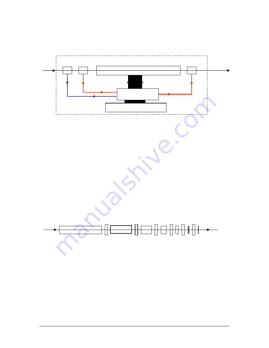
Figure 33 System diagram of polarization optimized PMD source. The DSP based circuit is used to 1)
process information from the polarimeters and control instructions from users, 2) instruct the PMD
generator to select desired PMD values, 3) control the PC to optimize the input SOP for various functions.
The PMD generator used in the PMDPro is based on General Photonics’ patent pending
ternary polarization rotation technology. The generator is constructed using a series of
birefrigent crystals, with a ternary polarization rotator sandwiched between each pair of
adjacent crystal segments, as shown in Figure 34. The crystals are arranged in descending
order, with lengths decreasing sequentially by a factor of 2. Each rotator is capable of
rotating the state of polarization (SOP) by +45, 0, or
−
45 degrees.
Rotator #1 Rotator #2
Rotator #N
Birefringent Crystals
Figure 34 The construction of a PMD generator made with birefringent crystals and ternary polarization
rotators which can rotate SOP in 3 ways.
When the rotator between two adjacent crystals rotates the SOP +45°, the optical axes of
the two crystals are aligned to produce the maximum combined DGD. When the rotator
between two adjacent crystals rotates the SOP
−
45°, the optical axes of the two crystals
are counter-aligned to produce the minimum combined DGD. When the rotator between
two adjacent crystals rotates the SOP 0° (no rotation), the optical axes of the two crystals
Document #: GP-UM-PMD-1000-21
Page 112 of 122


