GE
V
OLUSON
i / V
OLUSON
e
D
IRECTION
KTI106052, R
EVISION
10
S
ERVICE
M
ANUAL
10-16
Section 10-7 - Electrical Safety Tests
10-7-5
Grounding Continuity (Systems with Dock Cart only)
NOTE:
This test is not valid for stand-alone Voluson i / Voluson e systems and is only applicable when the
Voluson i / Voluson e portable ultrasound system is mounted on the Dock Cart.
Measure the resistance from the third pin of the attachment plug to the exposed metal parts of the
Dock Cart.
The ground wire resistance should be less than
0.2
ohms.
Reference the procedure in the IEC 60601-1-1.
10-7-5-1
Meter Procedure
Follow these steps to test the ground wire resistance.
1.) Turn the Voluson i / Voluson e unit OFF.
2.) Plug the unit into the meter, and the meter into the tested AC wall outlet.
3.) Plug the black chassis cable into the meter's “CHASSIS” connector and attach the black chassis
cable clamp to an exposed metal part of the Voluson i / Voluson e unit.
4.) Set the meter’s “FUNCTION” switch to the RESISTANCE position.
5.) Set the meter's “POLARITY” switch to the OFF (center) position.
6.) Measure and record the Ground wire resistance.
CAUTION
!! CAUTION:
Electric Shock Hazard!
The patient or operator MUST NOT come into contact with equipment during this test.
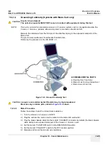
Figure 10-4 Ground Continuity Test
CAUTION
!! CAUTION:
Lacquer is an isolation barrier! Resistor may be high-impedance!
Measure only on blank parts, stated in
Figure 10-4
, above.
GROUND PIN
OHMMETER
ACCESSIBLE METAL PARTS
a) Mounting Plate Transformer
b) Blank screws from height adjustment
c) Blank screws at back side
OHMMETER
Содержание H48651KR
Страница 2: ......
Страница 11: ...GE VOLUSON i VOLUSON e DIRECTION KTI106052 REVISION 10 SERVICE MANUAL ix ZH CN KO ...
Страница 44: ...GE VOLUSON i VOLUSON e DIRECTION KTI106052 REVISION 10 SERVICE MANUAL xlii Table of Contents ...
Страница 514: ...GE VOLUSON i VOLUSON e DIRECTION KTI106052 REVISION 10 SERVICE MANUAL IV Index ...
Страница 515: ......

