GE
V
OLUSON
i / V
OLUSON
e
D
IRECTION
KTI106052, R
EVISION
10
S
ERVICE
M
ANUAL
3-42
Section 3-5 - Connection of Auxiliary Devices
3-5-3-9
Mounting large Peripherals (e.g., VCR)
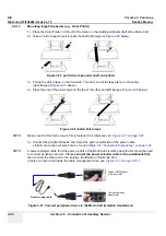
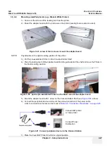
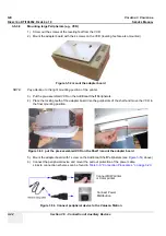
1.) Screw out the screws of the leveling feet from the VCR.
2.) Mount the adapter board with the 4 screws on the VCR (leveling feet are also mounted).
NOTE:
Pay attention to the right mounting position of the printer.
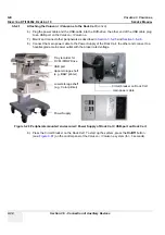
3.) Put the pre-assembled VCR on the Additional Shelf Peripherals.
4.) Place the locking teeth of the adapter board into the guide slots of the shelf and move the VCR in
the final mounting position.
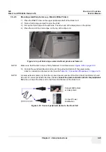
5.) Mount the adapter board with 1 screw on the Additional Shelf Peripherals (see
Figure 3-53
, above).
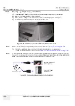
6.) Connect the peripheral device and mount the pull out protection of the power cable.
Links to connection schemes can be found in
Table 3-9, “Connection Procedures,” on page 3-23
.
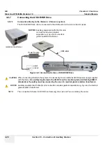
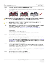
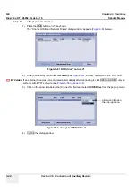
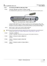
Figure 3-52 mount the adapter board
Figure 3-53 put the pre-assembled VCR on the Shelf / mount the adapter board
Figure 3-54 Connect peripheral device to the Voluson Station
Connect B/W printer
or Color printer
Connect Power
Distribution
Содержание H48651KR
Страница 2: ......
Страница 11: ...GE VOLUSON i VOLUSON e DIRECTION KTI106052 REVISION 10 SERVICE MANUAL ix ZH CN KO ...
Страница 44: ...GE VOLUSON i VOLUSON e DIRECTION KTI106052 REVISION 10 SERVICE MANUAL xlii Table of Contents ...
Страница 514: ...GE VOLUSON i VOLUSON e DIRECTION KTI106052 REVISION 10 SERVICE MANUAL IV Index ...
Страница 515: ......

