


GE M
EDICAL
S
YSTEMS
D
IRECTION
2392751-100, R
EVISION
3
V
IVID
™ 4 S
ERVICE
M
ANUAL
3-24
Section 3-5 - Completing the Hardware Installation
3-5-2
Connecting Peripherals
Peripheral devices, such as a VCR or printer, are connected to the Vivid™ 4 ultrasound unit using the
rear panel connectors. Ensure that all peripheral devices connected to the ultrasound unit comply with
national safety requirements for medical equipment, including IEC601, CSA22.2, AS3200.1 and UL544.
The Vivid™ 4
ultrasound unit can operate with one or more of the following types of on-board
peripherals:
•
VCR
•
Black & White (B/W) Printer
•
Color Printer (may be installed in side compartment)
•
HP Deskjet 6122 Color Printer
Note:
Each of the peripherals have European and US versions. For a complete list of recommended
peripherals, refer to the
Vivid™ 4 User Manual
. For information for each peripheral device, refer
to the manufacturer’s manual.
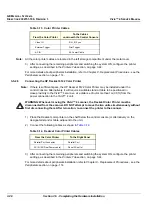
On-board peripherals must be connected to one of the two available auxiliary power supplies on the
right rear panel. The total load on both auxiliary AC outlets should not exceed 500 VA. This means
8 Amp @ 100-120V AC or 4 Amp @ 220-240V AC.
Voltages are set according to local country voltage, as described in the
For more details about peripherals installation, refer to
Chapter 8 - Replacement Procedures -
see
.
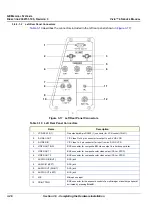
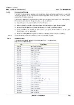
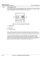
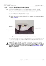
3-5-2-1
Rear Panel Connectors
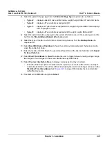
The Vivid™ 4 ultrasound unit is equipped with two rear panels that provide the connections for
peripheral devices, as shown in
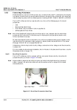
Note:
Right and left are determined from the front of the unit. Refer to the
section, on page 3-25, and to the
section, on page 3-26, for details
about each panel.
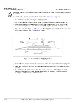
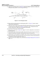
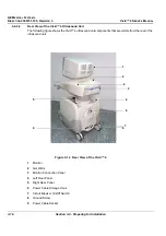
Figure 3-15 Rear Panel Connectors Rear View
Right Rear Panel
Left Rear Panel


