


GE M
EDICAL
S
YSTEMS
D
IRECTION
2392751-100, R
EVISION
3
V
IVID
™ 4 S
ERVICE
M
ANUAL
Chapter 5 - Components and Function (Theory)
5-9
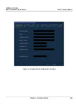
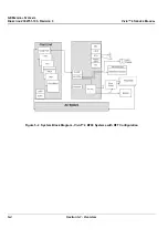
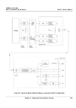
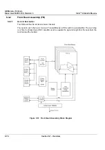
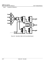
Figure 5-6 Front End Crate Block Diagram - RFT Configuration
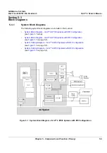
The Front End can be divided into two subsystems, as follows:
1.) The
Front End subsystem
which includes:
-
Front Board
-
MUX Board
-
BF64 (Beamformer Board)
2.) The
Mid Processors subsystem
which includes:
-
RFI (Radio Frequency Interface Board)
OR
*
FEC (Front End Controller Board)
*
RFT (Radio Frequency & Tissue Board)
*
IMP (Image Port).
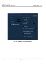
Front
Board
TR4 Boards
MUX
Board
64Ch
Beam Former
A/D
Board
RFT
Board
Image Port
Board
FEC
(Front End Controller)
Board
Power Supply
Tx P.S.
L.V P.S
Vingmed manufactured boards
I C bus
2
PCI2IP
I
2
C bus
FE bus
Pipeline
link
VME bus
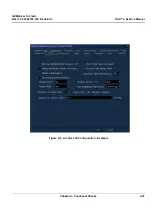
Front
Board
TR4 Boards
MUX
Board
64Ch
Beam Former
A/D
Board
RFT
Board
Image Port
Board
FEC
(Front End Controller)
Board
Power Supply
Tx P.S.
L.V P.S
Vingmed manufactured boards
I C bus
2
PCI2IP
I
2
C bus
FE bus
Pipeline
link
VME bus


