


GE M
EDICAL
S
YSTEMS
D
IRECTION
2392751-100, R
EVISION
3
V
IVID
™ 4 S
ERVICE
M
ANUAL
Chapter 8 - Replacement Procedures
8-9
8-2-6
Top Cover (Lower Section) Replacement Procedures
8-2-6-1
Tools
Use the appropriate Phillips-type screw drivers, and a wire cutter as indicated in the replacement
procedures for the lower section of the top cover.
8-2-6-2
Preparations
Shut down the Vivid™ 4 ultrasound unit, as described in
.
8-2-6-3
Top Cover Lower Section Removal Procedure
1) Remove the side covers, as described in the
Side Covers Replacement Procedures
2) Remove the rear cover, as described in the
Rear Cover Replacement Procedures
3) Raise the control console to its
maximum
height.
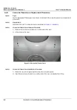
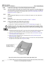
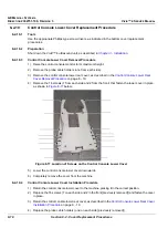
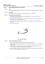
4) Remove the two screws located in the brackets underneath the lower section of the top cover, one
on either side of the unit, as shown below:
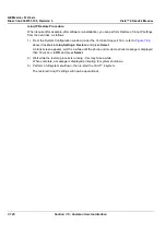
Figure 8-9 Top Cover (Lower Section) Screws
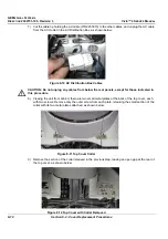
5) Remove the connectors panels cover, as described the
Connector Panels Cover Replacement
6) Unplug all the peripheral cables connected to the rear connector panels.
Note:
Pay attention to the location of each cable, as each one must be reconnected to its original
location during the installation process.
Screws


