GE M
EDICAL
S
YSTEMS
D
IRECTION
2392751-100, R
EVISION
3
V
IVID
™ 4 S
ERVICE
M
ANUAL
5-12
Section 5-1 - Overview
5-4-1-4-2
MLA-0 and MLA-1 Buses (RFI configuration only)
•
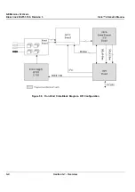
The Mid Processors are interconnected through a data bus system called the MLA-0 and MLA-1.
These are uni-directional buses, transporting data from the Beamformer to the Demodulator FPGA
on the RFI.
•
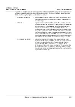
Data leaving the Demodulator FPGA have a tag indicating what type of data is transported; for
example,
tissue
,
Doppler
,
2D Flow
. Each of the remaining mid-processor components decode this
tag and when it matches their own address, the data is processed.
•
In 2D mode, data is typically transferred in vector blocks from the Demodulator FPGA. In Doppler
and Color Flow modes, data from one range gate is transferred.
5-4-1-5
Transmit Signal Path
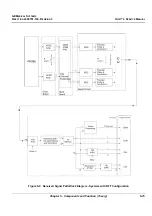
The transmit signal is configured via the operating mode that was selected by the user. When this mode
is selected, it sets those operating parameters for the FEC or RFI, and the FEC or RFI sends a signal
to the high voltage power supply (HVPS) to program one of the supplies (HVPS1 or HVPS2).
Once the signal is transmitted, it is received by the transmit pulsor (TP) which is a switching device that
will propagate the signal between different elements of the probe. The propagation of that signal
depends on the way in which the FEC (or RFI) programs the Front board RAM table.
The signal from the HVPS comes in to the TP; the TP then generates a signal to the probe (connected
to the Front board), in accordance with a command generated in Timing Pulse Generator (TPG). The
TPG operates according to tables in the RAM table - see
5-4-1-6
Received Signal Path
The receive signal is programmed according to the operating mode that was selected by the user. In some
cases the signal is received immediately after it has been transmitted, sometimes after a prescribed delay,
and in other cases at the same time as transmission (transmit/receive simultaneously).
Refer to
on page 5-15, as appropriate.
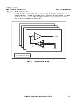
Figure 5-7 Transmit Signal Path Block Diagram
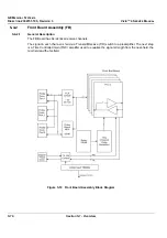
Front Board
Front Board

