


GE M
EDICAL
S
YSTEMS
D
IRECTION
2392751-100, R
EVISION
3
V
IVID
™ 4 S
ERVICE
M
ANUAL
8-108
Section 8-6 - Lower Section Components Replacement
8-6-9-4
Front Wheel Removal - Procedure 2
WARNING: When performing this procedure, the machine must be safely supported on two
wooden blocks (or on a jack capable of supporting the weight of the machine). Do not lean on
the machine, or leave it unattended without support, when the wheels have been removed.
Always remove and replace one wheel at a time, before attempting to remove the second wheel.
Note:
Before you begin, make sure you are working on a flat surface with the wheels facing the front
and the brake in the left (
locked
) position, preventing movement.
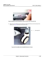
1) Remove the Vivid™ 4 front cover, as described in the
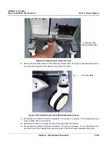
2) Remove the locking washer, located on the black wheel position bar, and lift the wheel position bar.
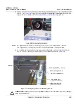
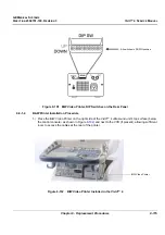
3) Using a flat screwdriver, push up and release the locking spring washer located in the center of the
transverse arm (wheel position bar), as shown in
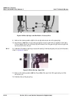
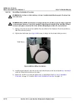
4.) Release the locking spring washer from the underside of each end of the transverse arm, as shown
in
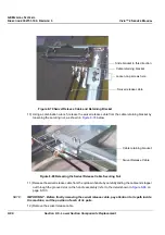
Figure 8-96 Releasing the Spring Washer from the End of the Transverse Arm
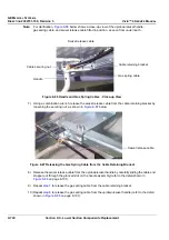
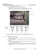
5.) Lifting the transverse arm upwards, unhook it from the central locking pin located above the brake
pedal and remove it completely. Refer to


