


GE M
EDICAL
S
YSTEMS
D
IRECTION
2392751-100, R
EVISION
3
V
IVID
™ 4 S
ERVICE
M
ANUAL
8-32
Section 8-3 - Control Console Components Replacement
8-3-7
Trackball Replacement Procedure
8-3-7-1
Tools
Use the appropriate flat and Phillips-type screw drivers, a wire cutter and the appropriate Hex wrench
keys as indicated in the trackball replacement procedure.
8-3-7-2
Preparation
Shut down the Vivid™ 4 ultrasound unit, as described in
.
8-3-7-3
Trackball Removal Procedure
1) Remove the control console lower rear cover, as described in the
2.) Remove the control console lower cover, as described in the
3) Remove the control console upper cover front, as described in the
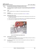
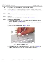
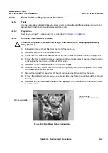
4) Unplug the four keyboard cables located at the bottom of the keyboard - see
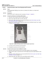
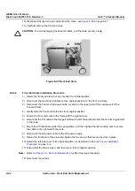
5) Loosen and remove the two M4 screws securing the keyboard matrix to the metal frame (one on
each of the
left
and
right
corners - see
6.) Loosen the M5 nut from the forked metal aligning plate (located in the center).
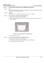
7.) Pull the keyboard away from the metal frame carefully releasing the forked metal aligning plate from
the central nut.
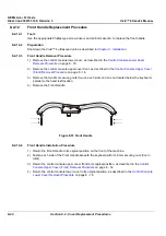
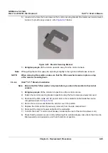
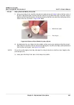
8) Disconnect the trackball cable from the trackball unit - see
9) Remove the two screws located on the bracket on either side of the trackball unit, and then remove
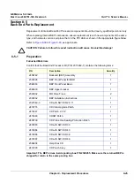
the trackball unit.
8-3-7-4
Trackball Installation Procedure
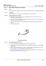
1) Return the trackball unit to its original location and insert the two screws located on the bracket on
either side of the trackball unit.
2) Connect the trackball cable to the trackball unit.
Figure 8-30 Trackball Removal


