


PRODUCT DESCRIPTION
GEK-106273L
MIF Digital Feeder Protection
3-31
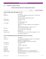
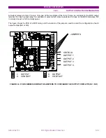
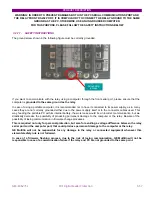
3.2.5. OUTPUT
CONTACTS
CONFIGURATION
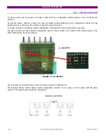
All output relays are form C relays. Only one of the two states of the form C relay is connected to the MIFII output
terminal. For each output relay it is possible to select which state is preferred to have at the MIFII terminals, NC
(normally closed) or NO (normally open).
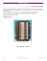
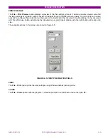
The figure shows the PCB of a MIFII relay, and the location of the jumpers used to select the configuration of each
output contact (NO or NC).
FIGURE 3.8. PCB SCHEME SHOWING THE JUMPERS TO CONFIGURE THE OUTPUT CONTACTS (NC / NO)
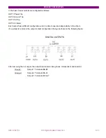
CRITICAL
OUTPUT 1
OUTPUT 2
OUTPUT 3
OUTPUT 4
C
O
C
OUTPUT
CONTACT
OUTPUT
CONTACT
O
JUMPERS
Содержание GEK-106273L
Страница 19: ...GETTING STARTED 1 12 MIF Digital Feeder Protection GEK 106273L ...
Страница 95: ...SETTINGS 5 38 MIF Digital Feeder Protection GEK 106273L ...
Страница 101: ...I O CONFIGURATION 6 44 MIF Digital Feeder Protection GEK 106273L ...
Страница 127: ...KEYPAD AND DISPLAY 8 26 MIF Digital Feeder Protection GEK 106273L ...
Страница 147: ...INSTALLATION AND MAINTENANCE 10 2 MIF Digital Feeder Protection GEK 106273L ...
Страница 154: ...ANNEX 1 THERMAL IMAGE UNIT GEK 106273L MIF Digital Feeder Protection 11 7 Figure A 1 1 THERMAL CURVE FOR τ1 3 MINUTES ...
Страница 155: ...ANNEX 1 THERMAL IMAGE UNIT 11 8 MIF Digital Feeder Protection GEK 106273L Figure A 1 2 THERMAL CURVES FOR τ1 3 MIN ...
Страница 199: ...ANNEX 5 HARMONIC FILTERING 15 4 MIF Digital Feeder Protection GEK 106273L ...