


PRODUCT DESCRIPTION
3-38
MIF Digital Feeder Protection
GEK-106273L
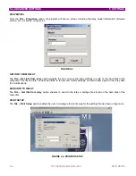
3.2.8. RS485
COMMUNICATIONS
PORT
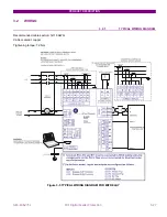
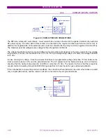
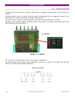
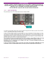
In addition to the RS232 port on the faceplate, the relay provides the user with an additional RS485 communication
port. RS485 data transmission and reception are accomplished over a single twisted pair with transmit and receive
data alternating over the same two wires. Through the use of these port, continuous monitoring and control from a
remote computer, SCADA system or PLC is possible.
To minimise errors from noise, the use of shielded twisted pair wire is recommended. For a correct operation, polarity
must be respected, although if it is not so, there is no danger to damage the unit. For instance, the relays must be
connected with all RS485 SDA terminals connected together, and all SDB terminals connected together. This may
result confusing sometimes, as the RS485 standard refers only to terminals named “A” and “B”, although many
devices use terminals named “+” and “-“. As a general rule, terminals “A” should be connected to terminals “-“, and
terminals “B” to “+”. There are exceptions to this rule, such as ALPS and DDS family relays. The GND terminal should
be connected to the common wire inside the shield, when provided. Otherwise, it should be connected to the shield.
To avoid loop currents, the shield should be grounded at one point only. Each relay should also be daisy chained to
the next one in the link. A maximum of 32 relays can be connected in this manner without exceeding driver capability.
For larger systems, additional serial channels must be added. It is also possible to use commercially available
repeaters to increase the number of relays on a single channel to more than 32. Do not use other connection
configuration different than the recommended.
Lightning strikes and ground surge currents can cause large momentary voltage differences between remote ends of
the communication link. For this reason, surge protection devices are internally provided. To ensure maximum
reliability, all equipment should have similar transient protection devices installed.
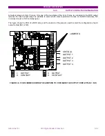
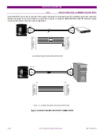
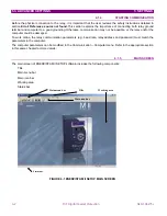
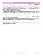
Figure 3-10 RS485 SERIAL CONNECTION (B6366H5)
M SERIES RELAY
(*)
Line terminations (120 ohm / 0.5 W + 1 nF / 100 V)
should be used when length of line exceeds 1 km.
M SERIES RELAY
ALPS & DTP
B12
B12
-
+
SDA /-
SDA
SDA
SDB
SDB
GND
GND
A12
A12
+
-
SDB /+
B11
B11
GND
GND
Zt (*)
Zt (*)
GND
Содержание GEK-106273L
Страница 19: ...GETTING STARTED 1 12 MIF Digital Feeder Protection GEK 106273L ...
Страница 95: ...SETTINGS 5 38 MIF Digital Feeder Protection GEK 106273L ...
Страница 101: ...I O CONFIGURATION 6 44 MIF Digital Feeder Protection GEK 106273L ...
Страница 127: ...KEYPAD AND DISPLAY 8 26 MIF Digital Feeder Protection GEK 106273L ...
Страница 147: ...INSTALLATION AND MAINTENANCE 10 2 MIF Digital Feeder Protection GEK 106273L ...
Страница 154: ...ANNEX 1 THERMAL IMAGE UNIT GEK 106273L MIF Digital Feeder Protection 11 7 Figure A 1 1 THERMAL CURVE FOR τ1 3 MINUTES ...
Страница 155: ...ANNEX 1 THERMAL IMAGE UNIT 11 8 MIF Digital Feeder Protection GEK 106273L Figure A 1 2 THERMAL CURVES FOR τ1 3 MIN ...
Страница 199: ...ANNEX 5 HARMONIC FILTERING 15 4 MIF Digital Feeder Protection GEK 106273L ...