


ANNEX 5 HARMONIC FILTERING
GEK-106273L
MIF Digital Feeder Protection
15-1
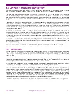
15. ANNEX 5. HARMONIC FILTERING
The present document intends to give an overview on how the MIF relay deals with analog signals, in order to
help determine whether the relay is appropriate for certain applications.
15.1
GENERAL PRINCIPLE OF OPERATION.
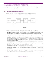
MIF relays, as the rest of our digital relays, are based on the following functional diagram:
Figure 1
Each of these blocks has its own functionality inside the general operation of the unit, as follows:
-
Transformer (CT/VT)
: It adapts the analog current and/or voltage signals to low level signals that can be
used by electronic devices. Additionally, they provide isolation between the environment and the relay.
-
Tap
: It turns current signals into voltage signals, which are better managed. Do not confuse with the tap
setting in the relay.
-
Antialiasing Filter
: It prevents high frequency signals (which cannot be recognised digitally) from entering
the analog-digital converter. The maximum breaking frequency for this filter is determined by the Nyquis
criterion, which states that the maximum frequency that can be recognised when sampling a signal is less
than half the sampling frequency.
In the MIF, the sampling is 16 times per cycle, that is, 800 Hz for a frequency set to 50 Hz, and 960 Hz for
a frequency set to 60 Hz.
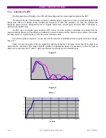
On the other hand, in order to obtain a reliable oscillography record, it is important to have a high breaking
frequency in this filter.
This filter does not intend to filter the harmonics, this is better done digitally.
In the MIF, the antialiasing filter has a breaking frequency of approx. 260 Hz.
-
Analog-Digital Converter
: It turns the analog signals into digital, so that they can be managed by a
microcontroller.
-
CPU
: It is the digital signal-processing unit; it takes tripping decisions, etc.
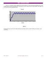
The CPU performs the DFT for current and voltage signals in order to obtain the vectors representing each
signal, which are used for all further calculations in the relay protection functions.
Содержание GEK-106273L
Страница 19: ...GETTING STARTED 1 12 MIF Digital Feeder Protection GEK 106273L ...
Страница 95: ...SETTINGS 5 38 MIF Digital Feeder Protection GEK 106273L ...
Страница 101: ...I O CONFIGURATION 6 44 MIF Digital Feeder Protection GEK 106273L ...
Страница 127: ...KEYPAD AND DISPLAY 8 26 MIF Digital Feeder Protection GEK 106273L ...
Страница 147: ...INSTALLATION AND MAINTENANCE 10 2 MIF Digital Feeder Protection GEK 106273L ...
Страница 154: ...ANNEX 1 THERMAL IMAGE UNIT GEK 106273L MIF Digital Feeder Protection 11 7 Figure A 1 1 THERMAL CURVE FOR τ1 3 MINUTES ...
Страница 155: ...ANNEX 1 THERMAL IMAGE UNIT 11 8 MIF Digital Feeder Protection GEK 106273L Figure A 1 2 THERMAL CURVES FOR τ1 3 MIN ...
Страница 199: ...ANNEX 5 HARMONIC FILTERING 15 4 MIF Digital Feeder Protection GEK 106273L ...