


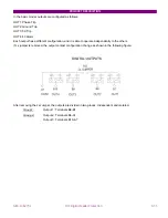


PRODUCT DESCRIPTION
GEK-106273L
MIF Digital Feeder Protection
3-25
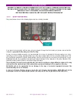
3.1.3.
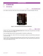
MODULE WITHDRAWAL / INSERTION
WARNING: MODULE WITHDRAWAL AND INSERTION SHALL ONLY BE PERFORMED
BY DULY QUALIFIED SERVICE PERSONEL WHEN CONTROL POWER HAS BEEN REMOVED FROM THE
UNIT
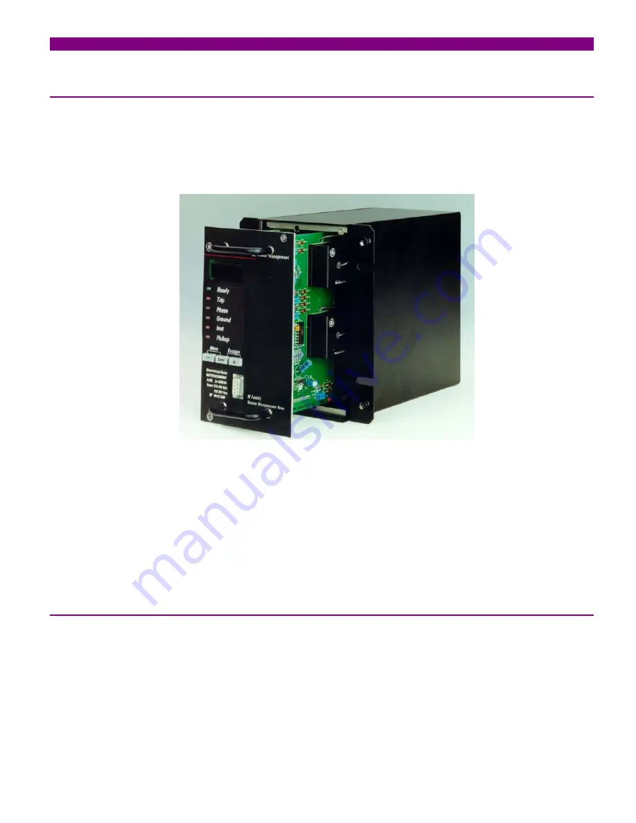
The modular design of the relay allows for the withdrawal and insertion of the module.
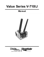
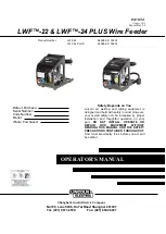
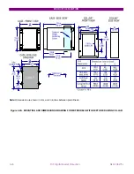
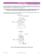
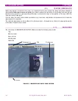
Figure 3-3: MIF WITHDRAWAL / INSERTION
WITHDRAWAL
: Remove the methacrylate cover on the faceplate, loosing the four screws located on the four
corners of the cover. Then loose the small screws that keep the faceplate in place and pull from the knobs located
on the upper and lower side of the faceplate. Before performing this action
control power must be removed from
the relay
. Current inputs are automatically shorted back in the terminal block when the module is withdrawn.
INSERTION:
Proceed inversely to the withdrawal procedure. Press the module firmly in the case, using the knobs,
until it is completely inserted. Once this is done, bolt the screws of the faceplate and replace the control power.
Check if the relay is fully operative. Finally, replace the methacrylate cover.
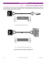
3.1.4.
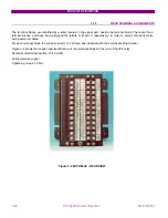
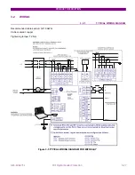
WIRING AND INTERNAL CONNECTIONS
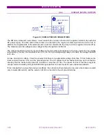
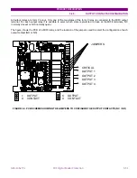
The electrical connection with the substation AC/DC wires is done on the three terminal blocks, at the rear part of the
relay case. Each terminal block has 12 terminals (M3, 3 mm diameter).
Current inputs are also located on one of the three terminal blocks, at the rear. This terminal block is designed to
withstand the secondary currents of the substation CTs. The internal wires taking the currents are of greater section
than the rest of the internal wires for the relay inputs. They have been designed to have the shortest length possible,
to minimise the burden in the primary CTs. Internal connections are done through pressing terminals. The internal
current wires are separated from the rest, to minimise the magnetic coupling (associated to high input currents) on
other internal wires carrying weaker signals.
Содержание GEK-106273L
Страница 19: ...GETTING STARTED 1 12 MIF Digital Feeder Protection GEK 106273L ...
Страница 95: ...SETTINGS 5 38 MIF Digital Feeder Protection GEK 106273L ...
Страница 101: ...I O CONFIGURATION 6 44 MIF Digital Feeder Protection GEK 106273L ...
Страница 127: ...KEYPAD AND DISPLAY 8 26 MIF Digital Feeder Protection GEK 106273L ...
Страница 147: ...INSTALLATION AND MAINTENANCE 10 2 MIF Digital Feeder Protection GEK 106273L ...
Страница 154: ...ANNEX 1 THERMAL IMAGE UNIT GEK 106273L MIF Digital Feeder Protection 11 7 Figure A 1 1 THERMAL CURVE FOR τ1 3 MINUTES ...
Страница 155: ...ANNEX 1 THERMAL IMAGE UNIT 11 8 MIF Digital Feeder Protection GEK 106273L Figure A 1 2 THERMAL CURVES FOR τ1 3 MIN ...
Страница 199: ...ANNEX 5 HARMONIC FILTERING 15 4 MIF Digital Feeder Protection GEK 106273L ...