Fronius VR 2000, Operating Instructions Manual
The Fronius VR 2000 brings advanced welding technology to your fingertips. With its intuitive interface and powerful capabilities, this innovative device ensures precise and efficient welding processes. Enhance your welding experience with our comprehensive Operating Instructions Manual, available for free download exclusively at manualshive.com.
Share
Download


Reviews:
No comments
Related manuals for VR 2000
MM 300-ES
Brand: Comparc Pages: 28
W64-1
Brand: WIA Pages: 28
BECMATIC 550
Brand: BecherAir Components Pages: 17

AKM 96RM-E
Brand: janitza Pages: 76
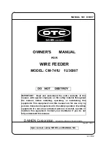
OTC CM-741U
Brand: Daihen Pages: 34

Dillon Conversion Kit
Brand: RCBS Pages: 12

Streamfeeder Value Series
Brand: Barry-Wehmiller Pages: 58
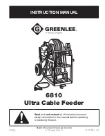
Greenlee 6810
Brand: Textron Pages: 26
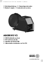
ABIDRIVE V2
Brand: Abicor Binzel Pages: 136
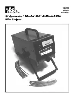
Stripmaster 950
Brand: IDEAL Pages: 16
GEK-106273L
Brand: GE Pages: 209

Power Feed 10 Robotic K1780-2
Brand: Lincoln Electric Pages: 28
76202
Brand: Lincoln Electric Pages: 13
K2536-6
Brand: Lincoln Electric Pages: 59
DADF-G1
Brand: Canon Pages: 154
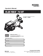
FLEX FEED 74 HT
Brand: Lincoln Electric Pages: 59

YW-50DNW
Brand: Panasonic Pages: 20
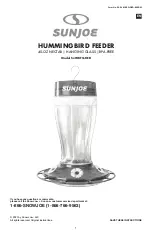
SJ-WBFG-RED
Brand: sunjoe Pages: 20


