


LOGIC CONFIGURATION
GEK-106273L
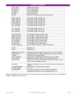
MIF Digital Feeder Protection
7-1
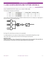
7. LOGIC CONFIGURATION (ONLY OPTION 2 MODELS)
7.1.1. LOGIC
DESCRIPTION
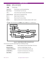
Using the ENERVISTA MII SETUP software, we can configure 4 different logics.
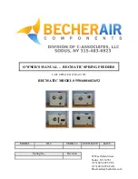
The default logic configuration is the following:
LOGIC CONFIGURATION
PICKUP TIMER
DROPOUT TIMER
1
S1 = Not defined
0
0
2
S1 = Not defined
0
0
3
S1 = Not defined
0
0
4
S1 = Not defined
0
0
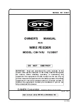
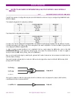
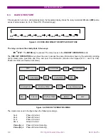
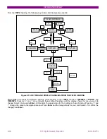
Logic functions are divided in several groups, besides
Not defined
function. We can configure up to eight signals in
the same Logic box with the following structure:
Each signal (S1...S8) has the same structure as the outputs/LEDs.
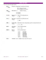
To configure a logic box, we can proceed in the same way as for the outputs/LEDs configuration per signal.
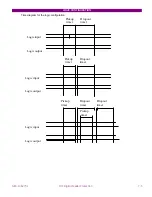
There are two timers, pickup and dropout timers, that can be assigned to each logic box.
IMPORTANT NOTE
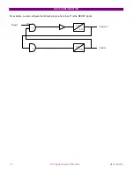
Signals must be used in order, starting with S1. If we wish to use more than one signal in the same AND, use
S2 first and then S3. If we wish to use another AND use AND 2 first, and then AND 3.
S1
S2
S3
S4
S5
S6
S7
S8
T
T
1
2
3
Содержание GEK-106273L
Страница 19: ...GETTING STARTED 1 12 MIF Digital Feeder Protection GEK 106273L ...
Страница 95: ...SETTINGS 5 38 MIF Digital Feeder Protection GEK 106273L ...
Страница 101: ...I O CONFIGURATION 6 44 MIF Digital Feeder Protection GEK 106273L ...
Страница 127: ...KEYPAD AND DISPLAY 8 26 MIF Digital Feeder Protection GEK 106273L ...
Страница 147: ...INSTALLATION AND MAINTENANCE 10 2 MIF Digital Feeder Protection GEK 106273L ...
Страница 154: ...ANNEX 1 THERMAL IMAGE UNIT GEK 106273L MIF Digital Feeder Protection 11 7 Figure A 1 1 THERMAL CURVE FOR τ1 3 MINUTES ...
Страница 155: ...ANNEX 1 THERMAL IMAGE UNIT 11 8 MIF Digital Feeder Protection GEK 106273L Figure A 1 2 THERMAL CURVES FOR τ1 3 MIN ...
Страница 199: ...ANNEX 5 HARMONIC FILTERING 15 4 MIF Digital Feeder Protection GEK 106273L ...