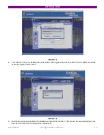
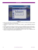
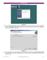
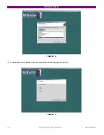


PRODUCT DESCRIPTION
2-6
MIF Digital Feeder Protection
GEK-106273L
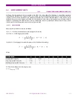
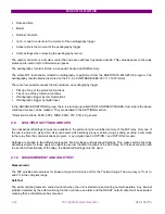
2.2.1.4. USER
CURVE
Response times for User Curve are as follows:
Where:
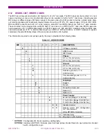
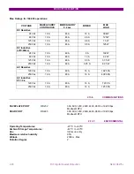
PARAMETERS
A
B
P
Q
K
Range
0 - 125
0-3
0-3
0-2
0-1.999
Step
0.001 0.001 0.001 0.001 0.001
Unit Sec.
Sec.
NA
NA
Sec.
Default
value
0.05 0 0.04 1 0
D
=
Time Dial setting (set in the relay by user).
V = I
/
I
pickup setting
> 1.05
I = Input
Current
T
=
Operate Time (sec)
A, P, Q, B, K
=
Constants defined in the standard, as follows:
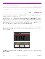
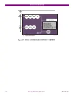
The settings available for the phase time overcurrent unit allows to: enable/disable the unit; set the pickup value
(between 0.1 - 2.4 times the rated current in case of 1/5 A ground, or 0.005-0.12 A in case of sensitive ground) and
set the current/time operating characteristic (type and time dial).
Note: The relay will use either IEC or ANSI curves, depending on the model.
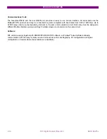
K
D
B
Q
V
D
A
T
P
+
+
−
=
*
*
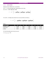
:
be
will
time
tripping
20.00,
V
1.05
For
trip.
a
not
but
pickup,
a
produce
will
unit
the
1.05,
V
1
For
<
≤
<
<
:
setting
the
times
20.00
for
as
same
the
be
will
time
tripping
the
V,
20.00
For
≤
K
D
B
Q
D
A
T
P
+
+
−
=
*
20
*
Содержание GEK-106273L
Страница 19: ...GETTING STARTED 1 12 MIF Digital Feeder Protection GEK 106273L ...
Страница 95: ...SETTINGS 5 38 MIF Digital Feeder Protection GEK 106273L ...
Страница 101: ...I O CONFIGURATION 6 44 MIF Digital Feeder Protection GEK 106273L ...
Страница 127: ...KEYPAD AND DISPLAY 8 26 MIF Digital Feeder Protection GEK 106273L ...
Страница 147: ...INSTALLATION AND MAINTENANCE 10 2 MIF Digital Feeder Protection GEK 106273L ...
Страница 154: ...ANNEX 1 THERMAL IMAGE UNIT GEK 106273L MIF Digital Feeder Protection 11 7 Figure A 1 1 THERMAL CURVE FOR τ1 3 MINUTES ...
Страница 155: ...ANNEX 1 THERMAL IMAGE UNIT 11 8 MIF Digital Feeder Protection GEK 106273L Figure A 1 2 THERMAL CURVES FOR τ1 3 MIN ...
Страница 199: ...ANNEX 5 HARMONIC FILTERING 15 4 MIF Digital Feeder Protection GEK 106273L ...