


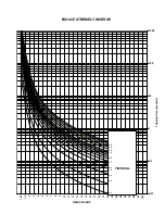


ANNEX 1 THERMAL IMAGE UNIT
GEK-106273L
MIF Digital Feeder Protection
11-5
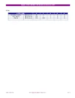
T
:
Time
τ
:
Time
constant
11.5
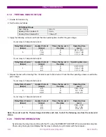
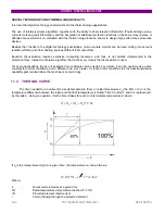
MIF THERMAL CURVES
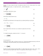
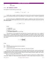
The equation for the temperature given before was:
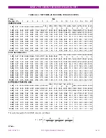
The MIF uses an equation, in which the tripping time is a function of the current flowing through the protected
element, thus eliminating all references to the temperatures. The heating time constant
τ
is the MIF is designated as
τ
1.
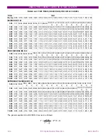
By means of the keypad (or ENERVISTA MII SETUP program), a tap/pickup current must be set in the relay.
If the current is greater than the programmed tap current, the thermal protection will trip after a period of time given by
the following equation:
Where:
t = Tripping time.
τ
1= Heating time constant.
I’ = I / I
tap
I =Current through the element.
I
tap
= Programmed tap/pickup current in the relay.
This equation can only be applied if the relay starts from a thermal zero status, that is, from a condition at
which a current I = 0 was flowing through it. If the relay had stabilised at a condition at which a given current was
flowing through it, the value of which is smaller than the rated current, and at a given moment the current increases
up to a value greater than the rated current, the tripping time from the moment the increase takes place is given by
the equation:
Where:
I
e
=
Ime / I
tap
Ime = Current at which the protected element had stabilised.
I
tap
=
Programmed tap current.
and the rest of the symbols have the same meaning as in the previous equation.
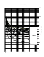
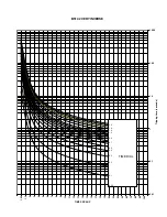
In the curves, the “Thermal Equivalent Current” (the greater current value from the current in the three phases)
is represented by the letter Ieq, and this is the value that the relay shows corresponding to the thermal image of the
protected element. The relay is running the thermal image for the three phases, but only the greater value is shown
in the display, as it is the one that will cause the trip.
When the protected element cools down, the time constant (Cooling Time Constant) may be different than the
heating time constant. For motors and generators applications, the heat transfer between the machine and the
)
1
.........(
)
/
(
*
)
1
(
*
2
)
1
(
IN
I
e
N
τ
θ
θ
−
−
=
))
1
'
/
'
ln(
*
2
2
1
−
=
I
I
t
τ
⎥
⎦
⎤
⎢
⎣
⎡
−
−
=
1
ln
*
2
2
2
1
I
I
I
t
e
τ
Содержание GEK-106273L
Страница 19: ...GETTING STARTED 1 12 MIF Digital Feeder Protection GEK 106273L ...
Страница 95: ...SETTINGS 5 38 MIF Digital Feeder Protection GEK 106273L ...
Страница 101: ...I O CONFIGURATION 6 44 MIF Digital Feeder Protection GEK 106273L ...
Страница 127: ...KEYPAD AND DISPLAY 8 26 MIF Digital Feeder Protection GEK 106273L ...
Страница 147: ...INSTALLATION AND MAINTENANCE 10 2 MIF Digital Feeder Protection GEK 106273L ...
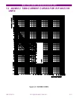
Страница 154: ...ANNEX 1 THERMAL IMAGE UNIT GEK 106273L MIF Digital Feeder Protection 11 7 Figure A 1 1 THERMAL CURVE FOR τ1 3 MINUTES ...
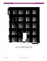
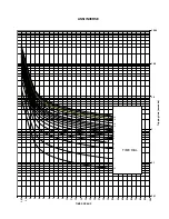
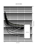
Страница 155: ...ANNEX 1 THERMAL IMAGE UNIT 11 8 MIF Digital Feeder Protection GEK 106273L Figure A 1 2 THERMAL CURVES FOR τ1 3 MIN ...
Страница 199: ...ANNEX 5 HARMONIC FILTERING 15 4 MIF Digital Feeder Protection GEK 106273L ...