


RELAY COMMISSIONING
9-4
MIF Digital Feeder Protection
GEK-106273L
•
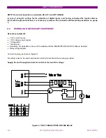
Using the ENERVISTA MII SETUP program, communicate with the relay and in the Status window check that the
communications are not lost at any time. Perform this test on both communications ports.
This test is carried out at the minimum and maximum voltage that the relay allows (
±
20% of the rated voltage).
9.8
RELAY SETTING
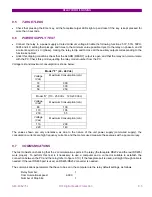
When the relay is shipped from our factory, it has a default set of settings, which are the starting point for the
following tests.
Since the MIF relay has a large number of settings, an exhaustive list of all the settings necessary for each test will
not be given here. Just the specific settings required for each test are indicated, and it can be supposed that the other
settings do not affect the test being performed.
We must take into account that these tests are only valid for the default factory configuration. Different configurations
involving modifications in certain elements, such as different contact configuration, will require a subsequent
modification of the test procedure.
9.9
CONTACT INPUTS
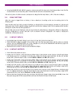
•
Sequentially apply the rated voltage to each input CC1 and CC2 (A8-A10 and A9-A10).
•
Check that when voltage is applied to one contact input, only this input gets active, and the other one remains
inactive. Use the INFORMATION menu on the faceplate or a PC and the ENERVISTA MII SETUP program to
easily check which input gets active for each test.
•
Repeat this test at minimum and maximum admissible voltage.
9.10
CONTACT OUTPUTS
•
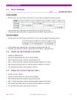
Check that all the outputs are open.
•
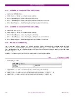
Enable only 51P function, and set its pickup and time delay to the minimum values. Inject a current through phase
A terminals equal to 2 x In (phase) to trip the relay. Check that the trip output (terminals A5-A6) and auxiliary
output OUT1 (terminals A7-B7) close, and the
PICKUP, PHASE
and
TRIP
LEDs light up.
•
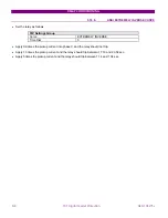
Enable only 51N function, and set its pickup and time delay to the minimum values. Inject a current through phase
A terminals equal to 2 x In (phase) to trip the relay. Check that the trip output (terminals A5-A6) and auxiliary
output OUT2 (terminals A7-B8) close, and the
PICK UP
,
GROUND
and
TRIP
LEDs light up.
•
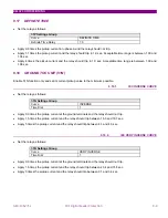
Enable only 50P function, and set its pickup to the minimum value. Inject a current through phase A terminals
equal to 2 x In (phase) to trip the relay. Check that the trip output (terminals A5-A6) and auxiliary output OUT3
(terminals B9-A7) close, and the
PICK UP
,
PHASE, INST
and
TRIP
LEDs light up.
•
Enable only function 49, and set its pickup to the minimum value. Inject a current through phase A terminals equal
to 2 x In (phase) making the relay trip. Check that the trip output (terminals A5-A6) and auxiliary output OUT4
(terminals B10-A7) close, and the
PICK UP
and
TRIP
LEDs light up.
•
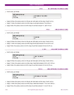
Remove the Power Supply from the relay and check that the Alarm Output Contact (terminals B5-B6) closes. Set
the power supply back to the relay terminals and check that the Alarm Output Contact opens.
Содержание GEK-106273L
Страница 19: ...GETTING STARTED 1 12 MIF Digital Feeder Protection GEK 106273L ...
Страница 95: ...SETTINGS 5 38 MIF Digital Feeder Protection GEK 106273L ...
Страница 101: ...I O CONFIGURATION 6 44 MIF Digital Feeder Protection GEK 106273L ...
Страница 127: ...KEYPAD AND DISPLAY 8 26 MIF Digital Feeder Protection GEK 106273L ...
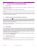
Страница 147: ...INSTALLATION AND MAINTENANCE 10 2 MIF Digital Feeder Protection GEK 106273L ...
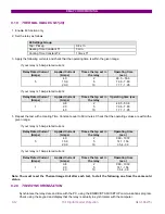
Страница 154: ...ANNEX 1 THERMAL IMAGE UNIT GEK 106273L MIF Digital Feeder Protection 11 7 Figure A 1 1 THERMAL CURVE FOR τ1 3 MINUTES ...
Страница 155: ...ANNEX 1 THERMAL IMAGE UNIT 11 8 MIF Digital Feeder Protection GEK 106273L Figure A 1 2 THERMAL CURVES FOR τ1 3 MIN ...
Страница 199: ...ANNEX 5 HARMONIC FILTERING 15 4 MIF Digital Feeder Protection GEK 106273L ...