


RELAY COMMISSIONING
9-2
MIF Digital Feeder Protection
GEK-106273L
NOTE: Do not test insulation on terminals B12, A12 and B11 (RS485)
In case of using AC voltage for the activation of digital inputs, and having connected the inputs common
(A10) with the ground terminal, it is necessary to remove this connection before testing insulation on group
3.
9.4
WIRING AND NECESSARY EQUIPMENT
Necessary equipment:
•
1 AC current source.
•
1 DC voltage power supply.
•
1 Stop-watch.
•
1 Multi-meter.
•
Optionally, it is advisable to have a PC available, with the ENERVISTA MII SETUP software installed.
•
Relay wiring diagram.
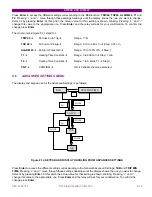
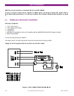
Connect the relay as shown in figure 9.1.
For safety reasons, the external protection earth terminal should be securely grounded.
Supply the unit through terminals A1 and A2 at the rated DC voltage.
Figure 9-1 TEST CONNECTIONS FOR MIF RELAY
Содержание GEK-106273L
Страница 19: ...GETTING STARTED 1 12 MIF Digital Feeder Protection GEK 106273L ...
Страница 95: ...SETTINGS 5 38 MIF Digital Feeder Protection GEK 106273L ...
Страница 101: ...I O CONFIGURATION 6 44 MIF Digital Feeder Protection GEK 106273L ...
Страница 127: ...KEYPAD AND DISPLAY 8 26 MIF Digital Feeder Protection GEK 106273L ...
Страница 147: ...INSTALLATION AND MAINTENANCE 10 2 MIF Digital Feeder Protection GEK 106273L ...
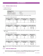
Страница 154: ...ANNEX 1 THERMAL IMAGE UNIT GEK 106273L MIF Digital Feeder Protection 11 7 Figure A 1 1 THERMAL CURVE FOR τ1 3 MINUTES ...
Страница 155: ...ANNEX 1 THERMAL IMAGE UNIT 11 8 MIF Digital Feeder Protection GEK 106273L Figure A 1 2 THERMAL CURVES FOR τ1 3 MIN ...
Страница 199: ...ANNEX 5 HARMONIC FILTERING 15 4 MIF Digital Feeder Protection GEK 106273L ...