


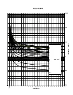
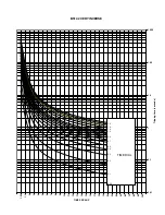
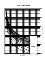

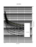

ANNEX 1 THERMAL IMAGE UNIT
11-4
MIF Digital Feeder Protection
GEK-106273L
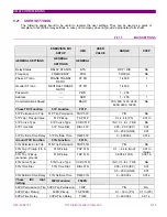
DIGITAL TECHNOLOGY AND THERMAL IMAGE RELAYS
It is clear that digital technology characteristics fit the thermal image applications.
The use of relatively simple algorithms, together with the ability to show relevant information (Thermal Image value,
currents metering, fault information) and the integration of additional protection functions in the same relay (inverse or
definite time overcurrent) co-ordinated with the thermal image function, allows to design high performance protective
devices.
Besides that, thanks to the digital technology possibilities, more accurate models can be used, taking into account
radiation effects, and other heating sources different that Joule effect.
Equation [9] evaluation requires extensive computing resources, and thus, is not directly implemented in the
protection relay. Instead, an iterative algorithm that mimics very closely the real equation is used.
For some applications, the use of separate time constants can be useful. For motors, it can be useful to use a time
constant for normal conditions, and a different one, much lower, for locked rotor conditions (as the heat transmission
capability gets reduced when the machine is not spinning).
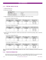
11.4
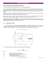
THERMAL CURVE
The time needed for an element to rise its temperature (from an initial temperature
θ
0
) the 63% of
θ
(
θ
is the
temperature difference between the initial and the final temperature) is called “Time Constant”, and it is represented
by the letter
τ
. Using an equation, it is the time it takes to reach an intermediate temperature
θ
i where:
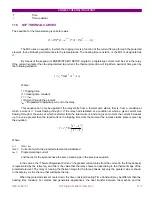
If
θ
0
is the temperature origin, at a given time, the temperature can be written as:
Where:
θ
:
Temperature increase at a given time
θ
N
:
Rated temperature (temperature reached if I = IN)
IN
:
Protected element rated current
I
:
Current flowing through the protected element
2
)
1
(
)
/
(
*
)
1
(
*
In
I
e
N
τ
θ
θ
−
=
63
.
0
*
)
(
0
0
θ
θ
θ
θ
−
+
=
∞
i
Содержание GEK-106273L
Страница 19: ...GETTING STARTED 1 12 MIF Digital Feeder Protection GEK 106273L ...
Страница 95: ...SETTINGS 5 38 MIF Digital Feeder Protection GEK 106273L ...
Страница 101: ...I O CONFIGURATION 6 44 MIF Digital Feeder Protection GEK 106273L ...
Страница 127: ...KEYPAD AND DISPLAY 8 26 MIF Digital Feeder Protection GEK 106273L ...
Страница 147: ...INSTALLATION AND MAINTENANCE 10 2 MIF Digital Feeder Protection GEK 106273L ...
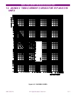
Страница 154: ...ANNEX 1 THERMAL IMAGE UNIT GEK 106273L MIF Digital Feeder Protection 11 7 Figure A 1 1 THERMAL CURVE FOR τ1 3 MINUTES ...
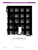
Страница 155: ...ANNEX 1 THERMAL IMAGE UNIT 11 8 MIF Digital Feeder Protection GEK 106273L Figure A 1 2 THERMAL CURVES FOR τ1 3 MIN ...
Страница 199: ...ANNEX 5 HARMONIC FILTERING 15 4 MIF Digital Feeder Protection GEK 106273L ...