MB89620 series
CHAPTER 3 CPU
47
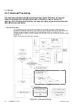
(1) After a reset, all interrupt requests are disabled.
Initialize the peripheral functions that are to generate interrupts in the peripheral function
initialization program, set the interrupt levels in the appropriate interrupt level setting
registers (ILR1, ILR2, ILR3), and start peripheral function.
The interrupt level can be set to 1, 2 or 3. Level 1 is the highest priority, followed by level 2.
Setting level 3 disables the interrupt for that peripheral function.
(2) Execute the main program (for multiple interrupts, execute the interrupt processing routine).
(3) The interrupt request flag bit (request FF) for a peripheral function is set to “1” when the
peripheral function generates an interrupt source. If the interrupt request enable bit for the
peripheral function is set to “enable” (enable FF = “1”), the peripheral function outputs the
interrupt request to the interrupt controller.
(4) The interrupt controller continuously monitors for interrupt requests from the peripheral
functions and passes the interrupt level of the current interrupt request with the highest
interrupt level to the CPU. The interrupt controller also evaluates the priority order if requests
with the same level are present simultaneously.
(5) If the interrupt level received by the CPU has a higher priority (a lower level value) than the
level set in the interrupt level bits in the condition code register (CCR: IL1, IL0), the CPU
checks the interrupt enable flag (CCR: I) and receives the interrupt if interrupts are enabled
(CCR: I = “1”).
(6) The CPU saves the contents of the program counter (PC) and program status (PS) on the
stack, reads the top address of the interrupt processing routine from the interrupt vector table
for the interrupt, updates the interrupt level bits in the condition code register (CCR: IL1, IL0)
with the received interrupt level, and starts execution of the interrupt processing routine.
(7) Finally, on execution of the RETI instruction, the CPU restores the program counter (PC) and
program status (PS) values saved on the stack and resumes execution from the instruction
following the last instruction executed before the interrupt.
Check:
As the interrupt request flag bit of a peripheral function is not cleared automatically when an
interrupt request is received, the bit must be cleared by the program (normally, by writing “0” to the
interrupt request flag bit) at interrupt processing routine.
Reference:
An interrupt wakes up the CPU from standby mode (low-power consumption). See Section
3.7, “Standby Modes (Low-power Consumption)” for details.
Note:
If the interrupt request flag bit is cleared at the top of the interrupt processing routine, the peripheral
function that has generated the interrupt becomes able to generate another interrupt during
execution of the interrupt processing routine (resetting the interrupt request flag bit). However, the
interrupts are not normally accepted until the current processing routine completes.
Содержание F2MC-8L MB89620 Series
Страница 8: ......
Страница 10: ...MB89620 series ...
Страница 11: ...vi MB89620 series ...
Страница 17: ...xii MB89620 series ...
Страница 18: ...xvi MB89620 series ...
Страница 30: ...MB89620 series CHAPTER 1 OVERVIEW 9 Memo ...
Страница 34: ...MB89620 series CHAPTER 1 OVERVIEW 13 Memo ...
Страница 42: ...MB89620 series CHAPTER 1 OVERVIEW 21 Memo ...
Страница 49: ...28 CHAPTER 1 OVERVIEW MB89620 series ...
Страница 62: ...MB89620 series CHAPTER 3 CPU 41 Memo ...
Страница 78: ...MB89620 series CHAPTER 3 CPU 57 Memo ...
Страница 82: ...MB89620 series CHAPTER 3 CPU 61 Memo ...
Страница 86: ...MB89620 series CHAPTER 3 CPU 65 Memo ...
Страница 90: ...MB89620 series CHAPTER 3 CPU 69 Memo ...
Страница 96: ...MB89620 series CHAPTER 3 CPU 75 Memo ...
Страница 122: ...MB89620 series CHAPTER 4 I O PORTS 101 Memo ...
Страница 144: ...MB89620 series CHAPTER 5 TIMEBASE TIMER 123 Memo ...
Страница 149: ...128 CHAPTER 5 TIMEBASE TIMER MB89620 series ...
Страница 157: ...136 CHAPTER 6 WATCHDOG TIMER MB89620 series ...
Страница 174: ...MB89620 series CHAPTER 7 8 BIT PWM TIMER 153 Memo ...
Страница 177: ...156 CHAPTER 7 8 BIT PWM TIMER MB89620 series ...
Страница 202: ...MB89620 series CHAPTER 9 16 BIT TIMER COUNTER 181 Memo ...
Страница 217: ...196 CHAPTER 9 16 BIT TIMER COUNTER MB89620 series ...
Страница 220: ...MB89620 series CHAPTER 10 8 BIT SERIAL I O SERIAL I O 1 AND SERIAL I O 2 199 Memo ...
Страница 228: ...MB89620 series CHAPTER 10 8 BIT SERIAL I O SERIAL I O 1 AND SERIAL I O 2 207 Memo ...
Страница 245: ...224 CHAPTER 10 8 BIT SERIAL I O SERIAL I O 1 AND SERIAL I O 2 MB89620 series ...
Страница 266: ...MB89620 series CHAPTER 13 A D CONVERTER 245 13 Memo ...
Страница 283: ...262 CHAPTER 13 A D CONVERTER MB89620 series ...
Страница 289: ...268 CHAPTER 14 CLOCK MONITOR FUNCTION MB89620 series ...
Страница 306: ...MB89620 series APPENDIX 285 APPEND Memo ...
Страница 319: ...298 APPENDIX MB89620 series Memo ...
Страница 321: ...2 ...
Страница 354: ......


