MB89620 series
CHAPTER 4 I/O PORTS
97
4.3 Port 2
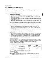
4.3.2 Operation of Port 2
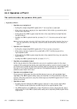
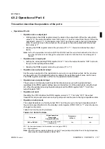
This section describes the operations of the port-2 in single-chip mode.
n
Operation of Port 2 (Single-chip Mode)
l
Operation as an output-only port
•
Writing data to the PDR2 register stores the data in the output latch and outputs the data to
the pin via the output buffer.
•
Reading the PDR2 register always returns the output latch data.
l
Operation at reset
Resetting the CPU in single-chip mode forcibly sets the buffer to “OFF” and sets the pins to the
high-impedance state. At the time when the CPU fetch the mode data (00
H
) from internal ROM
as part of the reset operation, output is enabled and the output ports output the “L” level.
Note:
A reset initializes the PDR2 register bits to all “0”s so that the pins output the “L” level.
l
Operation in stop mode
The output buffer is forcibly set to “OFF” and the pins go to the high-impedance state if the pin
state specification bit in the standby control register (STBC: SPL) is “1” when the device
changes to stop mode.
Table 4.3.2 lists the port 2 pin states.
SPL
: Pin state specification bit in the standby control register (STBC)
MOD0, MOD1 : Mode pins
Hi-z
: High impedance
Note:
A pull-up resistor cannot be set to port 2 as an option (without a pull-up resistor).
Table 4.3.2 Port 2 Pin State (Single-chip Mode)
Pin name
Normal operation
Sleep mode
Stop mode (SPL=0)
Stop mode
(SPL=1)
Reset
(MOD0, MOD1 = V
SS
, V
SS
)
P20/BUFC to P27/ALE
Output-only ports
Hi-z
Hi-z
Содержание F2MC-8L MB89620 Series
Страница 8: ......
Страница 10: ...MB89620 series ...
Страница 11: ...vi MB89620 series ...
Страница 17: ...xii MB89620 series ...
Страница 18: ...xvi MB89620 series ...
Страница 30: ...MB89620 series CHAPTER 1 OVERVIEW 9 Memo ...
Страница 34: ...MB89620 series CHAPTER 1 OVERVIEW 13 Memo ...
Страница 42: ...MB89620 series CHAPTER 1 OVERVIEW 21 Memo ...
Страница 49: ...28 CHAPTER 1 OVERVIEW MB89620 series ...
Страница 62: ...MB89620 series CHAPTER 3 CPU 41 Memo ...
Страница 78: ...MB89620 series CHAPTER 3 CPU 57 Memo ...
Страница 82: ...MB89620 series CHAPTER 3 CPU 61 Memo ...
Страница 86: ...MB89620 series CHAPTER 3 CPU 65 Memo ...
Страница 90: ...MB89620 series CHAPTER 3 CPU 69 Memo ...
Страница 96: ...MB89620 series CHAPTER 3 CPU 75 Memo ...
Страница 122: ...MB89620 series CHAPTER 4 I O PORTS 101 Memo ...
Страница 144: ...MB89620 series CHAPTER 5 TIMEBASE TIMER 123 Memo ...
Страница 149: ...128 CHAPTER 5 TIMEBASE TIMER MB89620 series ...
Страница 157: ...136 CHAPTER 6 WATCHDOG TIMER MB89620 series ...
Страница 174: ...MB89620 series CHAPTER 7 8 BIT PWM TIMER 153 Memo ...
Страница 177: ...156 CHAPTER 7 8 BIT PWM TIMER MB89620 series ...
Страница 202: ...MB89620 series CHAPTER 9 16 BIT TIMER COUNTER 181 Memo ...
Страница 217: ...196 CHAPTER 9 16 BIT TIMER COUNTER MB89620 series ...
Страница 220: ...MB89620 series CHAPTER 10 8 BIT SERIAL I O SERIAL I O 1 AND SERIAL I O 2 199 Memo ...
Страница 228: ...MB89620 series CHAPTER 10 8 BIT SERIAL I O SERIAL I O 1 AND SERIAL I O 2 207 Memo ...
Страница 245: ...224 CHAPTER 10 8 BIT SERIAL I O SERIAL I O 1 AND SERIAL I O 2 MB89620 series ...
Страница 266: ...MB89620 series CHAPTER 13 A D CONVERTER 245 13 Memo ...
Страница 283: ...262 CHAPTER 13 A D CONVERTER MB89620 series ...
Страница 289: ...268 CHAPTER 14 CLOCK MONITOR FUNCTION MB89620 series ...
Страница 306: ...MB89620 series APPENDIX 285 APPEND Memo ...
Страница 319: ...298 APPENDIX MB89620 series Memo ...
Страница 321: ...2 ...
Страница 354: ......


