MB89620 series
CHAPTER 3 CPU
81
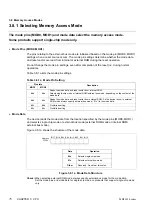
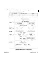
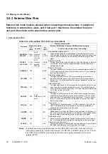
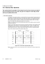
3.8 Memory Access Modes
3.8.3 External Bus Pin Control Register (BCTR)
The external bus pin control register (BCTR) specifies whether some of the port 2 pins
operate as output-only ports or as control pins for hold operation and buffer control.
This section describes the functions of the external bus pin control register (BCTR).
n
External Bus Pin Control Register (BCTR)
The external bus pin control register (BCTR) functions in external bus mode.
In single-chip mode, the content of the external bus pin control register (BCTR) is ignored and
the P20, P21, and P22 pins function as output-only ports. As the register is write-only, bit
manipulation instructions cannot be used.
Figure 3.8.3 shows the external bus pin control register (BCTR).
Figure 3.8.3 External Bus Pin Control Register (BCTR)
Table 3.8.3 lists the functions of each bit of the external bus pin control register (BCTR).
Table 3.8.3 External Bus Pin Control Register (BCTR) Bit
Bit
Function
Bit 7
Bit 6
Bit 5
Bit 4
Bit 3
Bit 2
Unused bits
•
The read value is indeterminate .
•
Writing has no effect on the operation.
Bit 1
HLD:
Hold enable bit
•
Selects the operation of the P21 and P22 pins in external bus mode.
•
Writing “0” to this bit specifies the P21 and P22 pins to function as output-only
ports. Writing “1” specifies P21 to function as a HAK output and P22 to function as
the HRQ input.
•
Reading this bit always returns “1” .
Bit 0
BUF:
Buffer control
enable bit
•
Selects the operation of the P20 pin in external bus mode.
•
Writing “0” to this bit specifies P20 to function as an output-only port. Writing “1”
specifies P20 to function as the BUFC output.
•
Reading this bit always returns “1” .
Address
Bit 7
Bit 6
Bit 5
Bit 4
Bit 3
Bit 2
Bit 1
Bit 0
Initial value
0005
H
—
—
—
—
—
—
HLD
BUF
XXXXXX01
B
W
W
BUF
Buffer control enable bit
0
Set P20 as a port.
1
Set P20 as the BUFC output.
HLD
Hold enable bit
0
Set P21 and P22 as ports.
1
Set P21 as the HAK output and P22
as the HRQ input.
W
: Write-only
—
: Unused
X
: Indeterminate
: Initial value
Содержание F2MC-8L MB89620 Series
Страница 8: ......
Страница 10: ...MB89620 series ...
Страница 11: ...vi MB89620 series ...
Страница 17: ...xii MB89620 series ...
Страница 18: ...xvi MB89620 series ...
Страница 30: ...MB89620 series CHAPTER 1 OVERVIEW 9 Memo ...
Страница 34: ...MB89620 series CHAPTER 1 OVERVIEW 13 Memo ...
Страница 42: ...MB89620 series CHAPTER 1 OVERVIEW 21 Memo ...
Страница 49: ...28 CHAPTER 1 OVERVIEW MB89620 series ...
Страница 62: ...MB89620 series CHAPTER 3 CPU 41 Memo ...
Страница 78: ...MB89620 series CHAPTER 3 CPU 57 Memo ...
Страница 82: ...MB89620 series CHAPTER 3 CPU 61 Memo ...
Страница 86: ...MB89620 series CHAPTER 3 CPU 65 Memo ...
Страница 90: ...MB89620 series CHAPTER 3 CPU 69 Memo ...
Страница 96: ...MB89620 series CHAPTER 3 CPU 75 Memo ...
Страница 122: ...MB89620 series CHAPTER 4 I O PORTS 101 Memo ...
Страница 144: ...MB89620 series CHAPTER 5 TIMEBASE TIMER 123 Memo ...
Страница 149: ...128 CHAPTER 5 TIMEBASE TIMER MB89620 series ...
Страница 157: ...136 CHAPTER 6 WATCHDOG TIMER MB89620 series ...
Страница 174: ...MB89620 series CHAPTER 7 8 BIT PWM TIMER 153 Memo ...
Страница 177: ...156 CHAPTER 7 8 BIT PWM TIMER MB89620 series ...
Страница 202: ...MB89620 series CHAPTER 9 16 BIT TIMER COUNTER 181 Memo ...
Страница 217: ...196 CHAPTER 9 16 BIT TIMER COUNTER MB89620 series ...
Страница 220: ...MB89620 series CHAPTER 10 8 BIT SERIAL I O SERIAL I O 1 AND SERIAL I O 2 199 Memo ...
Страница 228: ...MB89620 series CHAPTER 10 8 BIT SERIAL I O SERIAL I O 1 AND SERIAL I O 2 207 Memo ...
Страница 245: ...224 CHAPTER 10 8 BIT SERIAL I O SERIAL I O 1 AND SERIAL I O 2 MB89620 series ...
Страница 266: ...MB89620 series CHAPTER 13 A D CONVERTER 245 13 Memo ...
Страница 283: ...262 CHAPTER 13 A D CONVERTER MB89620 series ...
Страница 289: ...268 CHAPTER 14 CLOCK MONITOR FUNCTION MB89620 series ...
Страница 306: ...MB89620 series APPENDIX 285 APPEND Memo ...
Страница 319: ...298 APPENDIX MB89620 series Memo ...
Страница 321: ...2 ...
Страница 354: ......

