150
CHAPTER 7 8-BIT PWM TIMER
MB89620 series
7.
7
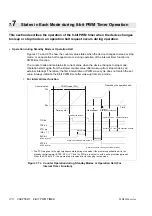
States in Each Mode during 8-bit PWM Timer Operation
This section describes the operation of the 8-bit PWM timer when the device changes
to sleep or stop mode or an operation halt request occurs during operation.
n
Operation during Standby Mode or Operation Halt
Figures 7.7a and 7.7b show the counter value states when the device changes to sleep or stop
mode, or an operation halt request occurs, during operation of the interval timer function or
PWM timer function.
The counter halts and maintains its current value when the device changes to stop mode.
Operation starts again from the stored counter value after wake-up from stop mode by an
external interrupt. Therefore, the first interval time or PWM wave cycle does not match the set
value. Always initialize the 8-bit PWM timer after wake-up from stop mode.
l
For interval timer function
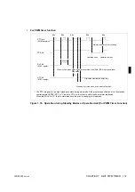
Figure 7.7a Counter Operation during Standby Modes or Operation Halt (For
Interval Timer Function)
Counter value
COMR value (FF
H
)
FF
H
00
H
Timer cycle
Time
TIR bit
TPE bit
PTO pin
SLP bit
Cleared by the program
Stop request
Oscillation
stabilization delay time
Cleared by the operation halt.
Operation halts
Operation restarts
(OE = “1”)
(STBC register)
STP bit
(STBC register)
Sleep mode
Wake-up from sleep mode by IRQ4.
Outputs an “L” level while operation is halted.
*
Stop mode
Wake-up from stop mode by an external interrupt.
* : The PTO pin goes to the high-impedance state during stop mode if the pin state specification bit in the
standby control register (STBC: SPL) is “1” and the PTO pin is not set to with a pull-up resistor (optional).
When the SPL bit is “0”, the pin maintains its value prior to changing to stop mode.
Содержание F2MC-8L MB89620 Series
Страница 8: ......
Страница 10: ...MB89620 series ...
Страница 11: ...vi MB89620 series ...
Страница 17: ...xii MB89620 series ...
Страница 18: ...xvi MB89620 series ...
Страница 30: ...MB89620 series CHAPTER 1 OVERVIEW 9 Memo ...
Страница 34: ...MB89620 series CHAPTER 1 OVERVIEW 13 Memo ...
Страница 42: ...MB89620 series CHAPTER 1 OVERVIEW 21 Memo ...
Страница 49: ...28 CHAPTER 1 OVERVIEW MB89620 series ...
Страница 62: ...MB89620 series CHAPTER 3 CPU 41 Memo ...
Страница 78: ...MB89620 series CHAPTER 3 CPU 57 Memo ...
Страница 82: ...MB89620 series CHAPTER 3 CPU 61 Memo ...
Страница 86: ...MB89620 series CHAPTER 3 CPU 65 Memo ...
Страница 90: ...MB89620 series CHAPTER 3 CPU 69 Memo ...
Страница 96: ...MB89620 series CHAPTER 3 CPU 75 Memo ...
Страница 122: ...MB89620 series CHAPTER 4 I O PORTS 101 Memo ...
Страница 144: ...MB89620 series CHAPTER 5 TIMEBASE TIMER 123 Memo ...
Страница 149: ...128 CHAPTER 5 TIMEBASE TIMER MB89620 series ...
Страница 157: ...136 CHAPTER 6 WATCHDOG TIMER MB89620 series ...
Страница 174: ...MB89620 series CHAPTER 7 8 BIT PWM TIMER 153 Memo ...
Страница 177: ...156 CHAPTER 7 8 BIT PWM TIMER MB89620 series ...
Страница 202: ...MB89620 series CHAPTER 9 16 BIT TIMER COUNTER 181 Memo ...
Страница 217: ...196 CHAPTER 9 16 BIT TIMER COUNTER MB89620 series ...
Страница 220: ...MB89620 series CHAPTER 10 8 BIT SERIAL I O SERIAL I O 1 AND SERIAL I O 2 199 Memo ...
Страница 228: ...MB89620 series CHAPTER 10 8 BIT SERIAL I O SERIAL I O 1 AND SERIAL I O 2 207 Memo ...
Страница 245: ...224 CHAPTER 10 8 BIT SERIAL I O SERIAL I O 1 AND SERIAL I O 2 MB89620 series ...
Страница 266: ...MB89620 series CHAPTER 13 A D CONVERTER 245 13 Memo ...
Страница 283: ...262 CHAPTER 13 A D CONVERTER MB89620 series ...
Страница 289: ...268 CHAPTER 14 CLOCK MONITOR FUNCTION MB89620 series ...
Страница 306: ...MB89620 series APPENDIX 285 APPEND Memo ...
Страница 319: ...298 APPENDIX MB89620 series Memo ...
Страница 321: ...2 ...
Страница 354: ......


