MB89620 series
CHAPTER 3 CPU
55
n
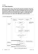
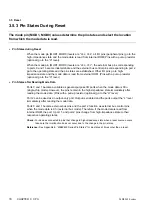
Mode Pins
When a reset source occurs, pins related to the external bus mode (port 0, port 1, and port 2)
are initialized according to the memory access mode specified by the mode pins (MOD1,
MOD0). The mode pin settings determine whether the mode data and reset vector are read
from internal or external ROM.
Do not change the mode pin settings, even after the reset has completed.
n
Mode Fetch
When the CPU wakes up from a reset, the CPU reads the mode data and reset vector from the
location (internal or external ROM) selected by the mode pin settings.
l
Mode data (address: FFFD
H
)
Selects single-chip mode or external bus mode. If external bus mode is selected when the mode
data is read from internal ROM, port 0, port 1, and port 2 become the external bus pins and the
pin states are modified.
Always set external bus mode if the mode data is read from external ROM.
Reference:
See Section 3.8, “Memory Access Modes” for details.
l
Reset vector (address: FFFE
H
(upper), FFFF
H
(lower))
Contains the address where execution is to start after completion of the reset. The CPU starts
executing instructions from the address contained in the reset vector.
n
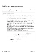
Oscillation Stabilization Delay Reset State
On products with power-on reset, the reset operation for a power-on reset or external reset in
stop mode starts after the oscillation stabilization delay time determined by the timebase timer.
If the CPU has not waked up from the external reset input when the delay time completes, the
reset operation does not start until the CPU wakes up from external reset.
As the oscillation stabilization delay time is also required when an external clock is used, a reset
requires that the external clock is input.
On products without power-on reset, the oscillation stabilization delay reset state is not used.
Therefore, for such products, hold the external reset pin (RST) at the “L” level to disable the
CPU operation until the source oscillation stabilizes.
n
Effect of Reset on RAM Contents
The contents of RAM are unchanged before and after a reset other than power-on reset.
As detection of an external reset is synchronized with the internal clock on products with power-
on reset, writes complete normally even if an external reset is input during a write operation.
However, if a reset occurs during writing of 16-bit data, it is possible that only the upper byte
write completes and the lower byte write does not occur.
If an external reset is input close to a write timing on products without power-on reset, the
contents of the write address cannot be assured.
Содержание F2MC-8L MB89620 Series
Страница 8: ......
Страница 10: ...MB89620 series ...
Страница 11: ...vi MB89620 series ...
Страница 17: ...xii MB89620 series ...
Страница 18: ...xvi MB89620 series ...
Страница 30: ...MB89620 series CHAPTER 1 OVERVIEW 9 Memo ...
Страница 34: ...MB89620 series CHAPTER 1 OVERVIEW 13 Memo ...
Страница 42: ...MB89620 series CHAPTER 1 OVERVIEW 21 Memo ...
Страница 49: ...28 CHAPTER 1 OVERVIEW MB89620 series ...
Страница 62: ...MB89620 series CHAPTER 3 CPU 41 Memo ...
Страница 78: ...MB89620 series CHAPTER 3 CPU 57 Memo ...
Страница 82: ...MB89620 series CHAPTER 3 CPU 61 Memo ...
Страница 86: ...MB89620 series CHAPTER 3 CPU 65 Memo ...
Страница 90: ...MB89620 series CHAPTER 3 CPU 69 Memo ...
Страница 96: ...MB89620 series CHAPTER 3 CPU 75 Memo ...
Страница 122: ...MB89620 series CHAPTER 4 I O PORTS 101 Memo ...
Страница 144: ...MB89620 series CHAPTER 5 TIMEBASE TIMER 123 Memo ...
Страница 149: ...128 CHAPTER 5 TIMEBASE TIMER MB89620 series ...
Страница 157: ...136 CHAPTER 6 WATCHDOG TIMER MB89620 series ...
Страница 174: ...MB89620 series CHAPTER 7 8 BIT PWM TIMER 153 Memo ...
Страница 177: ...156 CHAPTER 7 8 BIT PWM TIMER MB89620 series ...
Страница 202: ...MB89620 series CHAPTER 9 16 BIT TIMER COUNTER 181 Memo ...
Страница 217: ...196 CHAPTER 9 16 BIT TIMER COUNTER MB89620 series ...
Страница 220: ...MB89620 series CHAPTER 10 8 BIT SERIAL I O SERIAL I O 1 AND SERIAL I O 2 199 Memo ...
Страница 228: ...MB89620 series CHAPTER 10 8 BIT SERIAL I O SERIAL I O 1 AND SERIAL I O 2 207 Memo ...
Страница 245: ...224 CHAPTER 10 8 BIT SERIAL I O SERIAL I O 1 AND SERIAL I O 2 MB89620 series ...
Страница 266: ...MB89620 series CHAPTER 13 A D CONVERTER 245 13 Memo ...
Страница 283: ...262 CHAPTER 13 A D CONVERTER MB89620 series ...
Страница 289: ...268 CHAPTER 14 CLOCK MONITOR FUNCTION MB89620 series ...
Страница 306: ...MB89620 series APPENDIX 285 APPEND Memo ...
Страница 319: ...298 APPENDIX MB89620 series Memo ...
Страница 321: ...2 ...
Страница 354: ......


