234
CHAPTER 12 EXTERNAL INTERRUPT CIRCUIT (EDGE)
MB89620 series
12.
3
Structure of External Interrupt Circuit
This section describes the pins, pin block diagram, registers, and interrupt sources of
the external interrupt circuit.
n
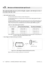
External Interrupt Circuit Pins
The external interrupt circuit uses four external interrupt pins.
The external interrupt pins can function either as external interrupt inputs (hysteresis inputs) or
as input-only ports.
Although the P60/INT0 to P63/INT3 pins continuously function as an external interrupt input, the
external interrupt circuit does not output interrupt requests if an interrupt output is disabled for
the pin. The pin states can be read directly from the port data register (PDR6) at any time.
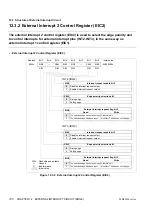
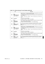
INT0 to INT3: The external interrupt circuit generates the interrupt request corresponding to the
pin when an edge of the specified polarity is input.
n
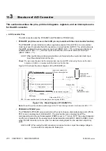
Block Diagram of External Interrupt Circuit Pins
Figure 12.3a Block Diagram of External Interrupt Circuit Pins
Note:
Pins with a pull-up resistor (optional) go to the pull-up state.
Table 12.3 External Interrupt Circuit Pins
External interrupt pin
When used as an external interrupt
input (interrupt request output enabled)
When used as an input-only port
(interrupt request output disabled)
P60/INT0
INT0 (EIC1: EIE0 = “1”)
P60 (EIC1: EIE0 = “0”)
P61/INT1
INT1 (EIC1: EIE1 = “1”)
P61 (EIC1: EIE1 = “0”)
P62/INT2
INT2 (EIC2: EIE2 = “1”)
P62 (EIC2: EIE2 = “0”)
P63/INT3
INT3 (EIC2: EIE3 = “1”)
P63 (EIC2: EIE3 = “0”)
PDR
(Port data register)
In
te
rn
a
l
d
a
ta
b
u
s
Pull-up resistor
(optional)
Approx. 50 k
Ω
/5.0 V
Pin
Input buffer
PDR read
To edge detector
P60/INT0 to P63/INT3
Содержание F2MC-8L MB89620 Series
Страница 8: ......
Страница 10: ...MB89620 series ...
Страница 11: ...vi MB89620 series ...
Страница 17: ...xii MB89620 series ...
Страница 18: ...xvi MB89620 series ...
Страница 30: ...MB89620 series CHAPTER 1 OVERVIEW 9 Memo ...
Страница 34: ...MB89620 series CHAPTER 1 OVERVIEW 13 Memo ...
Страница 42: ...MB89620 series CHAPTER 1 OVERVIEW 21 Memo ...
Страница 49: ...28 CHAPTER 1 OVERVIEW MB89620 series ...
Страница 62: ...MB89620 series CHAPTER 3 CPU 41 Memo ...
Страница 78: ...MB89620 series CHAPTER 3 CPU 57 Memo ...
Страница 82: ...MB89620 series CHAPTER 3 CPU 61 Memo ...
Страница 86: ...MB89620 series CHAPTER 3 CPU 65 Memo ...
Страница 90: ...MB89620 series CHAPTER 3 CPU 69 Memo ...
Страница 96: ...MB89620 series CHAPTER 3 CPU 75 Memo ...
Страница 122: ...MB89620 series CHAPTER 4 I O PORTS 101 Memo ...
Страница 144: ...MB89620 series CHAPTER 5 TIMEBASE TIMER 123 Memo ...
Страница 149: ...128 CHAPTER 5 TIMEBASE TIMER MB89620 series ...
Страница 157: ...136 CHAPTER 6 WATCHDOG TIMER MB89620 series ...
Страница 174: ...MB89620 series CHAPTER 7 8 BIT PWM TIMER 153 Memo ...
Страница 177: ...156 CHAPTER 7 8 BIT PWM TIMER MB89620 series ...
Страница 202: ...MB89620 series CHAPTER 9 16 BIT TIMER COUNTER 181 Memo ...
Страница 217: ...196 CHAPTER 9 16 BIT TIMER COUNTER MB89620 series ...
Страница 220: ...MB89620 series CHAPTER 10 8 BIT SERIAL I O SERIAL I O 1 AND SERIAL I O 2 199 Memo ...
Страница 228: ...MB89620 series CHAPTER 10 8 BIT SERIAL I O SERIAL I O 1 AND SERIAL I O 2 207 Memo ...
Страница 245: ...224 CHAPTER 10 8 BIT SERIAL I O SERIAL I O 1 AND SERIAL I O 2 MB89620 series ...
Страница 266: ...MB89620 series CHAPTER 13 A D CONVERTER 245 13 Memo ...
Страница 283: ...262 CHAPTER 13 A D CONVERTER MB89620 series ...
Страница 289: ...268 CHAPTER 14 CLOCK MONITOR FUNCTION MB89620 series ...
Страница 306: ...MB89620 series APPENDIX 285 APPEND Memo ...
Страница 319: ...298 APPENDIX MB89620 series Memo ...
Страница 321: ...2 ...
Страница 354: ......

