MB89620 series
CHAPTER 13 A/D CONVERTER
257
13
n
Activating Sense Function
l
Software activation
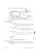
Figure 13.5c shows the settings required for software activation of the sense function.
Figure 13.5c Sense Function (Software Activation) Settings
On activation the sense function starts the operation of the sense function.
l
Continuous activation
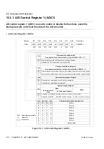
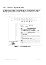
Figure 13.5d shows the settings required for continuous activation of the sense function.
Figure 13.5d Sense Function (Continuous Activation) Settings
When continuous activation is enabled, the rising edge of the selected input clock activates the
sense function, starting operation of the sense function. When continuous activation is disabled
(ADC2: EXT = “0”), continuous activation stops but software activation is available.
n
Operation of Sense Function
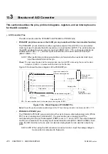
The following describes the operation of the sense function. From activation to completion of the
sense function requires approximately 12 instruction cycles.
(1) On activation, the sense function sets the conversion-in-progress flag bit (ADC1: ADMV =
“1”) and connects the sample hold circuit to the specified analog input pin.
(2) The internal sample hold capacitor captures the voltage at the analog input pin for
approximately 8 instruction cycles. The capacitor holds the voltage until the comparison
completes.
(3) The comparator compares the voltage captured by the sample hold capacitor with the
voltage corresponding to the value set in the ADCD register.
(4) When voltage comparison completes, the interrupt request flag bit is set (ADC1: ADI = “1”) if
the input voltage matches the condition specified by the compare condition setting bit
(ADC1: SIFM). The ADI bit does not change if the input voltage does not match the specified
condition or if the input voltage and set voltage are equal.
Note:
For the sense function, an interrupt request is not generated when comparison completes if the
comparison condition is not matched. Whether or not comparison has completed can be determined by
checking whether the conversion-in-progress flag bit (ADC1: ADMV) is “0”.
Bit 7
Bit 6
Bit 5
Bit 4
Bit 3
Bit 2
Bit 1
Bit 0
ADC1
ANS3
ANS2
ANS1
ANS0
ADI
ADMV
SIFM
AD
0
1
ADC2
—
—
—
ADCK
ADIE
ADMD
EXT
RESV1
×
1
0
1
ADC3
Sets the compare voltage.
: Used bit
×
: Unused bit
1 : Set “1”.
0 : Set “0”.
Bit 7
Bit 6
Bit 5
Bit 4
Bit 3
Bit 2
Bit 1
Bit 0
ADC1
ANS3
ANS2
ANS1
ANS0
ADI
ADMV
SIFM
AD
0
×
ADC2
—
—
—
ADCK
ADIE
ADMD
EXT
RESV1
1
1
1
ADC3
Sets the compare voltage.
: Used bit
×
: Unused bit
1 : Set “1”.
0 : Set “0”.
Содержание F2MC-8L MB89620 Series
Страница 8: ......
Страница 10: ...MB89620 series ...
Страница 11: ...vi MB89620 series ...
Страница 17: ...xii MB89620 series ...
Страница 18: ...xvi MB89620 series ...
Страница 30: ...MB89620 series CHAPTER 1 OVERVIEW 9 Memo ...
Страница 34: ...MB89620 series CHAPTER 1 OVERVIEW 13 Memo ...
Страница 42: ...MB89620 series CHAPTER 1 OVERVIEW 21 Memo ...
Страница 49: ...28 CHAPTER 1 OVERVIEW MB89620 series ...
Страница 62: ...MB89620 series CHAPTER 3 CPU 41 Memo ...
Страница 78: ...MB89620 series CHAPTER 3 CPU 57 Memo ...
Страница 82: ...MB89620 series CHAPTER 3 CPU 61 Memo ...
Страница 86: ...MB89620 series CHAPTER 3 CPU 65 Memo ...
Страница 90: ...MB89620 series CHAPTER 3 CPU 69 Memo ...
Страница 96: ...MB89620 series CHAPTER 3 CPU 75 Memo ...
Страница 122: ...MB89620 series CHAPTER 4 I O PORTS 101 Memo ...
Страница 144: ...MB89620 series CHAPTER 5 TIMEBASE TIMER 123 Memo ...
Страница 149: ...128 CHAPTER 5 TIMEBASE TIMER MB89620 series ...
Страница 157: ...136 CHAPTER 6 WATCHDOG TIMER MB89620 series ...
Страница 174: ...MB89620 series CHAPTER 7 8 BIT PWM TIMER 153 Memo ...
Страница 177: ...156 CHAPTER 7 8 BIT PWM TIMER MB89620 series ...
Страница 202: ...MB89620 series CHAPTER 9 16 BIT TIMER COUNTER 181 Memo ...
Страница 217: ...196 CHAPTER 9 16 BIT TIMER COUNTER MB89620 series ...
Страница 220: ...MB89620 series CHAPTER 10 8 BIT SERIAL I O SERIAL I O 1 AND SERIAL I O 2 199 Memo ...
Страница 228: ...MB89620 series CHAPTER 10 8 BIT SERIAL I O SERIAL I O 1 AND SERIAL I O 2 207 Memo ...
Страница 245: ...224 CHAPTER 10 8 BIT SERIAL I O SERIAL I O 1 AND SERIAL I O 2 MB89620 series ...
Страница 266: ...MB89620 series CHAPTER 13 A D CONVERTER 245 13 Memo ...
Страница 283: ...262 CHAPTER 13 A D CONVERTER MB89620 series ...
Страница 289: ...268 CHAPTER 14 CLOCK MONITOR FUNCTION MB89620 series ...
Страница 306: ...MB89620 series APPENDIX 285 APPEND Memo ...
Страница 319: ...298 APPENDIX MB89620 series Memo ...
Страница 321: ...2 ...
Страница 354: ......


