MB89620 series
CHAPTER 13 A/D CONVERTER
251
13
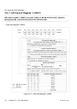
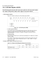
Table 13.3.1 A/D Control Register 1 (ADC1) Bits
Bit
Function
Bit 7
Bit 6
Bit 5
Bit 4
ANS3 to ANS0:
Analog input channel
selection bits
These bits select which of the AN0 to AN7 pins to use as the analog input pin.
When using software activation (ADC2: EXT = “0”), these bits can be modified to
at the same time as activating the A/D conversion or sense function (AD = “1”).
Check: Always set ANS3 to “0”.
If ANS3 is “1”, no pin is selected as the analog input pin. Also, disable
general-purpose port output corresponding to the analog input pin.
Do not modify these bits when the ADMV bit is set to “1”.
Note: Pins not used as analog inputs can be used as general-purpose ports.
Bit 3
ADI:
Interrupt request flag
bit
• For the A/D conversion function:
This bit is set to “1” when the A/D conversion is completed.
• For the sense function:
This bit is set to “1” when the input voltage satisfies the condition set in the
compare condition setting bit (SIFM).
• An interrupt request is output for either function when both this bit and the
interrupt request enable bit (ADC2: ADIE) are “1”.
• Writing “0” clears this bit. Writing “1” has no effect and does not change the bit
value.
Bit 2
ADMV:
Conversion-in-
progress flag bit
This bit indicates whether or not the A/D conversion function is currently
performing a conversion or the sense function is currently performing a voltage
comparison. The bit is set to “1” when a conversion or comparison is in progress.
Note: This bit is read-only. The write value has no meaning and has no effect on
the operation.
Bit 1
SIFM:
Compare condition
setting bit
• This bit has no meaning for the A/D conversion function.
• For the sense function:
This bit sets the comparison condition for the input voltage and compare
voltage that generates an interrupt source.
An interrupt request is generated (ADI = “1”) when the input voltage is less than
the compare voltage if the bit is “0”, and when the input voltage is greater than
the compare voltage if the bit is “1”.
No interrupt request is generated if the input voltage and compare voltage are
equal.
• When using software activation (ADC2: EXT = “0”), this bit can be modified to at
the same time as starting the sense function (AD = “1”).
Check: Do not modify these bits when the ADMV bit is set to “1”.
Bit 0
AD:
A/D converter
activation bit
• This bit activates the A/D conversion or sense function by software.
• Writing “1” to this bit activates the A/D conversion or sense function when
continuous activation is not specified (ADC2: EXT = “0”).
Check: • Writing “0” to this bit does not stop the A/D conversion or sense function.
The read value is always “0”.
• This bit has no meaning when continuous activation is specified.
Содержание F2MC-8L MB89620 Series
Страница 8: ......
Страница 10: ...MB89620 series ...
Страница 11: ...vi MB89620 series ...
Страница 17: ...xii MB89620 series ...
Страница 18: ...xvi MB89620 series ...
Страница 30: ...MB89620 series CHAPTER 1 OVERVIEW 9 Memo ...
Страница 34: ...MB89620 series CHAPTER 1 OVERVIEW 13 Memo ...
Страница 42: ...MB89620 series CHAPTER 1 OVERVIEW 21 Memo ...
Страница 49: ...28 CHAPTER 1 OVERVIEW MB89620 series ...
Страница 62: ...MB89620 series CHAPTER 3 CPU 41 Memo ...
Страница 78: ...MB89620 series CHAPTER 3 CPU 57 Memo ...
Страница 82: ...MB89620 series CHAPTER 3 CPU 61 Memo ...
Страница 86: ...MB89620 series CHAPTER 3 CPU 65 Memo ...
Страница 90: ...MB89620 series CHAPTER 3 CPU 69 Memo ...
Страница 96: ...MB89620 series CHAPTER 3 CPU 75 Memo ...
Страница 122: ...MB89620 series CHAPTER 4 I O PORTS 101 Memo ...
Страница 144: ...MB89620 series CHAPTER 5 TIMEBASE TIMER 123 Memo ...
Страница 149: ...128 CHAPTER 5 TIMEBASE TIMER MB89620 series ...
Страница 157: ...136 CHAPTER 6 WATCHDOG TIMER MB89620 series ...
Страница 174: ...MB89620 series CHAPTER 7 8 BIT PWM TIMER 153 Memo ...
Страница 177: ...156 CHAPTER 7 8 BIT PWM TIMER MB89620 series ...
Страница 202: ...MB89620 series CHAPTER 9 16 BIT TIMER COUNTER 181 Memo ...
Страница 217: ...196 CHAPTER 9 16 BIT TIMER COUNTER MB89620 series ...
Страница 220: ...MB89620 series CHAPTER 10 8 BIT SERIAL I O SERIAL I O 1 AND SERIAL I O 2 199 Memo ...
Страница 228: ...MB89620 series CHAPTER 10 8 BIT SERIAL I O SERIAL I O 1 AND SERIAL I O 2 207 Memo ...
Страница 245: ...224 CHAPTER 10 8 BIT SERIAL I O SERIAL I O 1 AND SERIAL I O 2 MB89620 series ...
Страница 266: ...MB89620 series CHAPTER 13 A D CONVERTER 245 13 Memo ...
Страница 283: ...262 CHAPTER 13 A D CONVERTER MB89620 series ...
Страница 289: ...268 CHAPTER 14 CLOCK MONITOR FUNCTION MB89620 series ...
Страница 306: ...MB89620 series APPENDIX 285 APPEND Memo ...
Страница 319: ...298 APPENDIX MB89620 series Memo ...
Страница 321: ...2 ...
Страница 354: ......

