MB89620 series
CHAPTER 8 PULSE WIDTH COUNT TIMER (PWC)
171
l
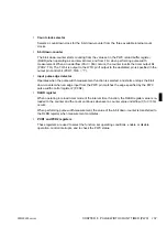
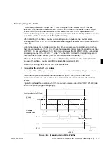
One-shot timer mode
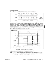
Figure 8.5c shows the settings required to operate in one-shot timer mode.
Figure 8.5c Interval Timer Function (One-shot Timer Mode) Settings
On activation, the RLBR register value is loaded to the counter and the counter starts counting-
down on the rising edge of the selected count clock. When the counter value underflows (01
H
→
00
H
), the counter inverts the timer output bit (PCR2: TO) value, automatically clears the counter
operation enable bit (PCR1: EN = “0”) to stop counter operation, and sets the underflow (01
H
→
00
H
) interrupt request flag bit (PCR1: UF = “1”) on the next rising edge of the count clock.
Figure 8.5d shows the operation in one-shot timer mode.
Figure 8.5d Operation in One-shot Timer Mode
Check:
Do not modify PCR2 when the counter is operating (PCR1: EN = “1”).
Notes: •
The UF bit is set to “1” if a counter value underflows (01
H
→
00
H
), regardless of the value of the
interrupt request enable bit (PCR1: IE).
•
When the counter is stopped (PCR1: EN = “0”) while the interval timer function is selected, the TO
bit maintains the value it had immediately before the counter stopped.
Bit 7
Bit 6
Bit 5
Bit 4
Bit 3
Bit 2
Bit 1
Bit 0
PCR1
EN
TOE
IE
—
—
UF
IR
BF
1
1
×
×
PCR2
FC
RM
TO
—
C1
C0
W1
W2
0
1
×
×
RLBR
Sets interval time (counter initial value).
: Used bit
×
: Unused bit
1 : Set “1”.
0 : Set “0”.
Counter value
FF
H
80
H
00
H
Timer cycle
Cleared by the program
Time
UF bit
EN bit
TOE bit
WTO pin
RLBR value
(FF
H
)
(TO bit)
Automatic clear
Reactivate
Invert
Reactivates with the initial value unchanged (“0”)
For an initial value of “1” on activation
*: If the PWC reload buffer register (RLBR) value is modified during operation, the new value is used from the next cycle.
Automatic clear
Automatic clear
Reactivate
RLBR value modified (FF
H
→
80
H
)
*
Содержание F2MC-8L MB89620 Series
Страница 8: ......
Страница 10: ...MB89620 series ...
Страница 11: ...vi MB89620 series ...
Страница 17: ...xii MB89620 series ...
Страница 18: ...xvi MB89620 series ...
Страница 30: ...MB89620 series CHAPTER 1 OVERVIEW 9 Memo ...
Страница 34: ...MB89620 series CHAPTER 1 OVERVIEW 13 Memo ...
Страница 42: ...MB89620 series CHAPTER 1 OVERVIEW 21 Memo ...
Страница 49: ...28 CHAPTER 1 OVERVIEW MB89620 series ...
Страница 62: ...MB89620 series CHAPTER 3 CPU 41 Memo ...
Страница 78: ...MB89620 series CHAPTER 3 CPU 57 Memo ...
Страница 82: ...MB89620 series CHAPTER 3 CPU 61 Memo ...
Страница 86: ...MB89620 series CHAPTER 3 CPU 65 Memo ...
Страница 90: ...MB89620 series CHAPTER 3 CPU 69 Memo ...
Страница 96: ...MB89620 series CHAPTER 3 CPU 75 Memo ...
Страница 122: ...MB89620 series CHAPTER 4 I O PORTS 101 Memo ...
Страница 144: ...MB89620 series CHAPTER 5 TIMEBASE TIMER 123 Memo ...
Страница 149: ...128 CHAPTER 5 TIMEBASE TIMER MB89620 series ...
Страница 157: ...136 CHAPTER 6 WATCHDOG TIMER MB89620 series ...
Страница 174: ...MB89620 series CHAPTER 7 8 BIT PWM TIMER 153 Memo ...
Страница 177: ...156 CHAPTER 7 8 BIT PWM TIMER MB89620 series ...
Страница 202: ...MB89620 series CHAPTER 9 16 BIT TIMER COUNTER 181 Memo ...
Страница 217: ...196 CHAPTER 9 16 BIT TIMER COUNTER MB89620 series ...
Страница 220: ...MB89620 series CHAPTER 10 8 BIT SERIAL I O SERIAL I O 1 AND SERIAL I O 2 199 Memo ...
Страница 228: ...MB89620 series CHAPTER 10 8 BIT SERIAL I O SERIAL I O 1 AND SERIAL I O 2 207 Memo ...
Страница 245: ...224 CHAPTER 10 8 BIT SERIAL I O SERIAL I O 1 AND SERIAL I O 2 MB89620 series ...
Страница 266: ...MB89620 series CHAPTER 13 A D CONVERTER 245 13 Memo ...
Страница 283: ...262 CHAPTER 13 A D CONVERTER MB89620 series ...
Страница 289: ...268 CHAPTER 14 CLOCK MONITOR FUNCTION MB89620 series ...
Страница 306: ...MB89620 series APPENDIX 285 APPEND Memo ...
Страница 319: ...298 APPENDIX MB89620 series Memo ...
Страница 321: ...2 ...
Страница 354: ......

