MB89620 series
CHAPTER 12 EXTERNAL INTERRUPT CIRCUIT (EDGE)
239
12
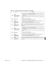
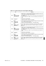
Table 12.3.2 External Interrupt 2 Control Register (EIC2) Bits
Bit
Function
Bit 7
EIR3:
External interrupt
request flag bit 3
• This bit is set to “1” when the edge selected by the edge polarity selection bit 3
(SEL3) is input to an external interrupt pin (INT3).
• An interrupt request is output when both this bit and the interrupt request enable
bit 3 (EIE3) are “1”.
• Writing “0” clears this bit. Writing “1” has no effect and does not change the bit
value.
Bit 6
Unused bit
• The read value is indeterminate.
• Writing to this bit has no effect on the operation.
Bit 5
SEL3:
Edge polarity
selection bit 3
• This bit selects the edge polarity that triggers interrupts when detected on pulses
input to external interrupt pin (INT3).
• A value of “0” selects rising edges and “1” selects falling edges.
Bit 4
EIE3:
Interrupt request
enable bit 3
This bit enables or disables an interrupt request output to the CPU. An interrupt
request is output when both this bit and the external interrupt request flag bit 3
(EIR3) are “1”.
Bit 3
EIR2:
External interrupt
request flag bit 2
• This bit is set to “1” when the edge selected by the edge polarity selection bit 2
(SEL2) is input to an external interrupt pin (INT2).
• An interrupt request is output when both this bit and the interrupt request enable
bit 2 (EIE2) are “1”.
• Writing “0” clears this bit. Writing “1” has no effect and does not change the bit
value.
Bit 2
Unused bit
• The read value is indeterminate.
• Writing to this bit has no effect on the operation.
Bit 1
SEL2:
Edge polarity
selection bit 2
• This bit selects the edge polarity that triggers interrupts when detected on pulses
input to external interrupt pin (INT2).
• A value of “0” selects rising edges and “1” selects falling edges.
Bit 0
EIE2:
Interrupt request
enable bit 2
This bit enables or disables an interrupt request output to the CPU. An interrupt
request is output when both this bit and the external interrupt request flag bit 2
(EIR2) are “1”.
Содержание F2MC-8L MB89620 Series
Страница 8: ......
Страница 10: ...MB89620 series ...
Страница 11: ...vi MB89620 series ...
Страница 17: ...xii MB89620 series ...
Страница 18: ...xvi MB89620 series ...
Страница 30: ...MB89620 series CHAPTER 1 OVERVIEW 9 Memo ...
Страница 34: ...MB89620 series CHAPTER 1 OVERVIEW 13 Memo ...
Страница 42: ...MB89620 series CHAPTER 1 OVERVIEW 21 Memo ...
Страница 49: ...28 CHAPTER 1 OVERVIEW MB89620 series ...
Страница 62: ...MB89620 series CHAPTER 3 CPU 41 Memo ...
Страница 78: ...MB89620 series CHAPTER 3 CPU 57 Memo ...
Страница 82: ...MB89620 series CHAPTER 3 CPU 61 Memo ...
Страница 86: ...MB89620 series CHAPTER 3 CPU 65 Memo ...
Страница 90: ...MB89620 series CHAPTER 3 CPU 69 Memo ...
Страница 96: ...MB89620 series CHAPTER 3 CPU 75 Memo ...
Страница 122: ...MB89620 series CHAPTER 4 I O PORTS 101 Memo ...
Страница 144: ...MB89620 series CHAPTER 5 TIMEBASE TIMER 123 Memo ...
Страница 149: ...128 CHAPTER 5 TIMEBASE TIMER MB89620 series ...
Страница 157: ...136 CHAPTER 6 WATCHDOG TIMER MB89620 series ...
Страница 174: ...MB89620 series CHAPTER 7 8 BIT PWM TIMER 153 Memo ...
Страница 177: ...156 CHAPTER 7 8 BIT PWM TIMER MB89620 series ...
Страница 202: ...MB89620 series CHAPTER 9 16 BIT TIMER COUNTER 181 Memo ...
Страница 217: ...196 CHAPTER 9 16 BIT TIMER COUNTER MB89620 series ...
Страница 220: ...MB89620 series CHAPTER 10 8 BIT SERIAL I O SERIAL I O 1 AND SERIAL I O 2 199 Memo ...
Страница 228: ...MB89620 series CHAPTER 10 8 BIT SERIAL I O SERIAL I O 1 AND SERIAL I O 2 207 Memo ...
Страница 245: ...224 CHAPTER 10 8 BIT SERIAL I O SERIAL I O 1 AND SERIAL I O 2 MB89620 series ...
Страница 266: ...MB89620 series CHAPTER 13 A D CONVERTER 245 13 Memo ...
Страница 283: ...262 CHAPTER 13 A D CONVERTER MB89620 series ...
Страница 289: ...268 CHAPTER 14 CLOCK MONITOR FUNCTION MB89620 series ...
Страница 306: ...MB89620 series APPENDIX 285 APPEND Memo ...
Страница 319: ...298 APPENDIX MB89620 series Memo ...
Страница 321: ...2 ...
Страница 354: ......


