72
CHAPTER 3 CPU
MB89620 series
3.7 Standby Modes (Low-power Consumption)
3.7.4 State Transition Diagram
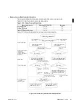
This section shows the state transition diagram for when a reset or interrupt operation
is performed during normal operation (RUN state) or during a standby mode (sleep or
stop mode).
n
Products with Power-on Reset
Figure 3.7.4a State Transition Diagram for Products with Power-on Reset
n
Products without Power-on Reset
Figure 3.7.4b State Transition Diagram for Products without Power-on Reset
(10)
(9)
(8)
(7)
(1)
(2)
(4)
(3)
(6)
(5)
Power on
Oscillation
stabilization delay
reset state
Oscillation
stabilization delay
Reset state
RUN state
Stop mode
Sleep mode
(1)
: Wake up from reset input
(2)
: Reset source (multiple)
(3)
: Change to sleep mode by setting the standby control register (STBC: SLP=1).
(4)
: External reset input
(5)
: Change to stop mode by setting the standby control register (STBC: STP=1).
(6)
: Interrupt request
(7)
: External interrupt request
(8) (9)
: Timebase timer overflow (oscillation stabilization delay time complete)
(10) (11) : External reset input
Power-on reset
(11)
(9)
(8)
(7)
(1)
(2)
(4)
(3)
(6)
(5)
Power on
Oscillation
stabilization delay
Reset state
RUN state
Sleep mode
(1)
: Wake up from reset input
(2)
: Reset source (multiple)
(3)
: Change to sleep mode by setting the standby control register (STBC: SLP=1).
(4)
: External reset input
(5)
: Change to stop mode by setting the standby control register (STBC: STP=1).
(6)
: Interrupt request
(7)
: External interrupt request
(8)
: Timebase timer overflow (oscillation stabilization delay time complete)
(9) (10) (11): External reset input (for the length of the oscillation stabilization delay time)
(10)
(11)
Stop mode
Содержание F2MC-8L MB89620 Series
Страница 8: ......
Страница 10: ...MB89620 series ...
Страница 11: ...vi MB89620 series ...
Страница 17: ...xii MB89620 series ...
Страница 18: ...xvi MB89620 series ...
Страница 30: ...MB89620 series CHAPTER 1 OVERVIEW 9 Memo ...
Страница 34: ...MB89620 series CHAPTER 1 OVERVIEW 13 Memo ...
Страница 42: ...MB89620 series CHAPTER 1 OVERVIEW 21 Memo ...
Страница 49: ...28 CHAPTER 1 OVERVIEW MB89620 series ...
Страница 62: ...MB89620 series CHAPTER 3 CPU 41 Memo ...
Страница 78: ...MB89620 series CHAPTER 3 CPU 57 Memo ...
Страница 82: ...MB89620 series CHAPTER 3 CPU 61 Memo ...
Страница 86: ...MB89620 series CHAPTER 3 CPU 65 Memo ...
Страница 90: ...MB89620 series CHAPTER 3 CPU 69 Memo ...
Страница 96: ...MB89620 series CHAPTER 3 CPU 75 Memo ...
Страница 122: ...MB89620 series CHAPTER 4 I O PORTS 101 Memo ...
Страница 144: ...MB89620 series CHAPTER 5 TIMEBASE TIMER 123 Memo ...
Страница 149: ...128 CHAPTER 5 TIMEBASE TIMER MB89620 series ...
Страница 157: ...136 CHAPTER 6 WATCHDOG TIMER MB89620 series ...
Страница 174: ...MB89620 series CHAPTER 7 8 BIT PWM TIMER 153 Memo ...
Страница 177: ...156 CHAPTER 7 8 BIT PWM TIMER MB89620 series ...
Страница 202: ...MB89620 series CHAPTER 9 16 BIT TIMER COUNTER 181 Memo ...
Страница 217: ...196 CHAPTER 9 16 BIT TIMER COUNTER MB89620 series ...
Страница 220: ...MB89620 series CHAPTER 10 8 BIT SERIAL I O SERIAL I O 1 AND SERIAL I O 2 199 Memo ...
Страница 228: ...MB89620 series CHAPTER 10 8 BIT SERIAL I O SERIAL I O 1 AND SERIAL I O 2 207 Memo ...
Страница 245: ...224 CHAPTER 10 8 BIT SERIAL I O SERIAL I O 1 AND SERIAL I O 2 MB89620 series ...
Страница 266: ...MB89620 series CHAPTER 13 A D CONVERTER 245 13 Memo ...
Страница 283: ...262 CHAPTER 13 A D CONVERTER MB89620 series ...
Страница 289: ...268 CHAPTER 14 CLOCK MONITOR FUNCTION MB89620 series ...
Страница 306: ...MB89620 series APPENDIX 285 APPEND Memo ...
Страница 319: ...298 APPENDIX MB89620 series Memo ...
Страница 321: ...2 ...
Страница 354: ......

