170
CHAPTER 8 PULSE WIDTH COUNT TIMER (PWC)
MB89620 series
8.
5
Operation of Interval Timer Function
This section describes the operation of the interval timer function of the pulse width
count timer.
n
Operation of Interval Timer Function
The interval timer function can operate as a continuous timer (reload timer mode), or as a timer
that operates for one cycle and then stops (one-shot mode).
l
Reload timer mode
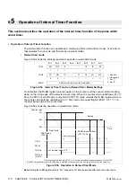
Figure 8.5a shows the settings required to operate in reload timer mode.
Figure 8.5a Interval Timer Function (Reload Timer Mode) Settings
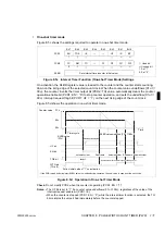
On activation, the RLBR register value is loaded to the counter and the counter starts counting-
down on the rising edge of the selected count clock. When the counter value underflows (01
H
→
00
H
), the PWC inverts the timer output bit (PCR2: TO) value, reloads the RLBR register value to
the counter, and sets the underflow (01
H
→
00
H
) interrupt request flag bit (PCR1: UF = “1”) on
the next rising edge of the count clock.
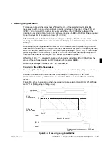
Figure 8.5b shows the operation in reload timer mode.
Figure 8.5b Operation in Reload Timer Mode
Note:
Setting the RLBR register value to “01
H
” causes the TO bit to be inverted after each count clock cycle.
Bit 7
Bit 6
Bit 5
Bit 4
Bit 3
Bit 2
Bit 1
Bit 0
PCR1
EN
TOE
IE
—
—
UF
IR
BF
1
1
×
×
PCR2
FC
RM
TO
—
C1
C0
W1
W2
0
0
×
×
RLBR
Sets interval time (counter initial value).
: Used bit
×
: Unused bit
1 : Set “1”.
0 : Set “0”.
Counter value
FF
H
80
H
00
H
Timer cycle
Cleared by the program
Time
UF bit
EN bit
TOE bit
WTO pin
RLBR value
(FF
H
)
RLBR value modified*
(FF
H
→
80
H
)
Reload
(TO bit)
For an initial value of “0”
When the output pin control bit (TOE) is “0”, the pin operates as a general-purpose I/O port (P36).
*: If the PWC reload buffer register (RLBR) value is modified during operation, the new value is used from the next cycle.
Содержание F2MC-8L MB89620 Series
Страница 8: ......
Страница 10: ...MB89620 series ...
Страница 11: ...vi MB89620 series ...
Страница 17: ...xii MB89620 series ...
Страница 18: ...xvi MB89620 series ...
Страница 30: ...MB89620 series CHAPTER 1 OVERVIEW 9 Memo ...
Страница 34: ...MB89620 series CHAPTER 1 OVERVIEW 13 Memo ...
Страница 42: ...MB89620 series CHAPTER 1 OVERVIEW 21 Memo ...
Страница 49: ...28 CHAPTER 1 OVERVIEW MB89620 series ...
Страница 62: ...MB89620 series CHAPTER 3 CPU 41 Memo ...
Страница 78: ...MB89620 series CHAPTER 3 CPU 57 Memo ...
Страница 82: ...MB89620 series CHAPTER 3 CPU 61 Memo ...
Страница 86: ...MB89620 series CHAPTER 3 CPU 65 Memo ...
Страница 90: ...MB89620 series CHAPTER 3 CPU 69 Memo ...
Страница 96: ...MB89620 series CHAPTER 3 CPU 75 Memo ...
Страница 122: ...MB89620 series CHAPTER 4 I O PORTS 101 Memo ...
Страница 144: ...MB89620 series CHAPTER 5 TIMEBASE TIMER 123 Memo ...
Страница 149: ...128 CHAPTER 5 TIMEBASE TIMER MB89620 series ...
Страница 157: ...136 CHAPTER 6 WATCHDOG TIMER MB89620 series ...
Страница 174: ...MB89620 series CHAPTER 7 8 BIT PWM TIMER 153 Memo ...
Страница 177: ...156 CHAPTER 7 8 BIT PWM TIMER MB89620 series ...
Страница 202: ...MB89620 series CHAPTER 9 16 BIT TIMER COUNTER 181 Memo ...
Страница 217: ...196 CHAPTER 9 16 BIT TIMER COUNTER MB89620 series ...
Страница 220: ...MB89620 series CHAPTER 10 8 BIT SERIAL I O SERIAL I O 1 AND SERIAL I O 2 199 Memo ...
Страница 228: ...MB89620 series CHAPTER 10 8 BIT SERIAL I O SERIAL I O 1 AND SERIAL I O 2 207 Memo ...
Страница 245: ...224 CHAPTER 10 8 BIT SERIAL I O SERIAL I O 1 AND SERIAL I O 2 MB89620 series ...
Страница 266: ...MB89620 series CHAPTER 13 A D CONVERTER 245 13 Memo ...
Страница 283: ...262 CHAPTER 13 A D CONVERTER MB89620 series ...
Страница 289: ...268 CHAPTER 14 CLOCK MONITOR FUNCTION MB89620 series ...
Страница 306: ...MB89620 series APPENDIX 285 APPEND Memo ...
Страница 319: ...298 APPENDIX MB89620 series Memo ...
Страница 321: ...2 ...
Страница 354: ......


