240
CHAPTER 12 EXTERNAL INTERRUPT CIRCUIT (EDGE)
MB89620 series
12.
4
External Interrupt Circuit Interrupts
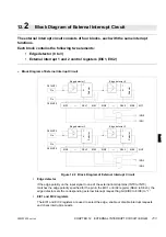
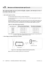
The external interrupt circuit can generate interrupt requests when it detects a
specified edge on the signal input to an external interrupt pin.
n
Interrupts for External Interrupt Circuit Operation
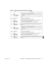
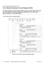
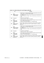
When a specified edge on an external interrupt input is detected, corresponding external
interrupt request flag bit (EIC1, EIC2: EIR0 to EIR3) is set to “1”. At this time, an interrupt
requests (IRQ0 to IRQ3) to the CPU are generated if the corresponding interrupt request enable
bit is enabled (EIC1, EIC2: EIE0 to EIE3 = “1”). Write “0” to the corresponding external interrupt
request flag bit in the interrupt processing routine to clear the interrupt request.
Check:
When enabling interrupts (EIE0 to EIE3 = “1”) after wake-up from a reset, always clear the
corresponding external interrupt request flag bit (EIR0 to EIR3 = “0”) at the same time.
Interrupt processing cannot return if the external interrupt request flag bit is “1” and the interrupt
request enable bit is enabled. In the interrupt processing routine, always clear the external
interrupt request flag bit.
Notes: •
Wake-up from stop mode by an interrupt is possible using only the external interrupt circuit.
•
An interrupt request is generated immediately if the external interrupt request flag bit is “1” when
the interrupt request enable bit is changed from disabled to enabled (“0”
→
“1”).
n
Register and Vector Table for External Interrupt Circuit Interrupts
Reference:
See Section 3.4.2, “Interrupt Processing” for details on the interrupts operation.
Table 12.4 Register and Vector Table for External Interrupt Circuit Interrupts
Interrupt
Interrupt level setting register
Vector table address
Register
Setting bits
Upper
Lower
IRQ0
ILR1 (007C
H
)
L01 (Bit 1)
L00 (Bit 0)
FFFA
H
FFFB
H
IRQ1
L11 (Bit 3)
L10 (Bit 2)
FFF8
H
FFF9
H
IRQ2
L21 (Bit 5)
L20 (Bit 4)
FFF6
H
FFF7
H
IRQ3
L31 (Bit 7)
L30 (Bit 6)
FFF4
H
FFF5
H
Содержание F2MC-8L MB89620 Series
Страница 8: ......
Страница 10: ...MB89620 series ...
Страница 11: ...vi MB89620 series ...
Страница 17: ...xii MB89620 series ...
Страница 18: ...xvi MB89620 series ...
Страница 30: ...MB89620 series CHAPTER 1 OVERVIEW 9 Memo ...
Страница 34: ...MB89620 series CHAPTER 1 OVERVIEW 13 Memo ...
Страница 42: ...MB89620 series CHAPTER 1 OVERVIEW 21 Memo ...
Страница 49: ...28 CHAPTER 1 OVERVIEW MB89620 series ...
Страница 62: ...MB89620 series CHAPTER 3 CPU 41 Memo ...
Страница 78: ...MB89620 series CHAPTER 3 CPU 57 Memo ...
Страница 82: ...MB89620 series CHAPTER 3 CPU 61 Memo ...
Страница 86: ...MB89620 series CHAPTER 3 CPU 65 Memo ...
Страница 90: ...MB89620 series CHAPTER 3 CPU 69 Memo ...
Страница 96: ...MB89620 series CHAPTER 3 CPU 75 Memo ...
Страница 122: ...MB89620 series CHAPTER 4 I O PORTS 101 Memo ...
Страница 144: ...MB89620 series CHAPTER 5 TIMEBASE TIMER 123 Memo ...
Страница 149: ...128 CHAPTER 5 TIMEBASE TIMER MB89620 series ...
Страница 157: ...136 CHAPTER 6 WATCHDOG TIMER MB89620 series ...
Страница 174: ...MB89620 series CHAPTER 7 8 BIT PWM TIMER 153 Memo ...
Страница 177: ...156 CHAPTER 7 8 BIT PWM TIMER MB89620 series ...
Страница 202: ...MB89620 series CHAPTER 9 16 BIT TIMER COUNTER 181 Memo ...
Страница 217: ...196 CHAPTER 9 16 BIT TIMER COUNTER MB89620 series ...
Страница 220: ...MB89620 series CHAPTER 10 8 BIT SERIAL I O SERIAL I O 1 AND SERIAL I O 2 199 Memo ...
Страница 228: ...MB89620 series CHAPTER 10 8 BIT SERIAL I O SERIAL I O 1 AND SERIAL I O 2 207 Memo ...
Страница 245: ...224 CHAPTER 10 8 BIT SERIAL I O SERIAL I O 1 AND SERIAL I O 2 MB89620 series ...
Страница 266: ...MB89620 series CHAPTER 13 A D CONVERTER 245 13 Memo ...
Страница 283: ...262 CHAPTER 13 A D CONVERTER MB89620 series ...
Страница 289: ...268 CHAPTER 14 CLOCK MONITOR FUNCTION MB89620 series ...
Страница 306: ...MB89620 series APPENDIX 285 APPEND Memo ...
Страница 319: ...298 APPENDIX MB89620 series Memo ...
Страница 321: ...2 ...
Страница 354: ......

