MB89620 series
CHAPTER 4 I/O PORTS
91
n
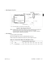
Block Diagram of Port 0 and 1 Pin (Single-chip Mode)
Figure 4.2 Block Diagram of Port 0 and 1 Pin (Single-chip Mode)
n
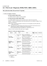
Port 0 and 1 Registers
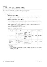
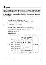
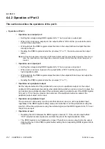
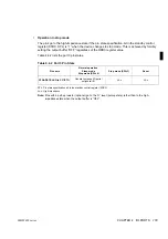
The port 0 registers consist of PDR0 and DDR0. The port 1 registers consist of PDR1 and
DDR1. However, accessing these registers in external bus mode has no meaning.
Each bit in these registers has a one-to-one relationship with a port 0 and 1 pin respectively.
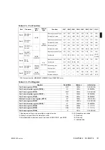
Table 4.2b shows the correspondence between pins and registers for ports 0 and 1.
Table 4.2b Correspondence
between
Pin and Register for Ports 0 and 1
Port
Correspondence between register bit and pin
Port 0
PDR0, DDR0
Bit 7
Bit 6
Bit 5
Bit 4
Bit 3
Bit 2
Bit 1
Bit 0
Corresponding pin
P07
P06
P05
P04
P03
P02
P01
P00
Port 1
PDR1, DDR1
Bit 7
Bit 6
Bit 5
Bit 4
Bit 3
Bit 2
Bit 1
Bit 0
Corresponding pin
P17
P16
P15
P14
P13
P12
P11
P10
PDR (Port data register)
DDR
In
te
rn
a
l
d
a
ta
b
u
s
PDR read
PDR read (for bit manipulation instructions)
Output latch
PDR write
DDR write (Port data direction register)
Stop mode (SPL=1)
Input buffer
Output buffer
Pull-up resistor
(optional)
Approx. 50 k
Ω
/5.0 V
Pin
SPL: Pin state specification bit in the standby control register (STBC)
Содержание F2MC-8L MB89620 Series
Страница 8: ......
Страница 10: ...MB89620 series ...
Страница 11: ...vi MB89620 series ...
Страница 17: ...xii MB89620 series ...
Страница 18: ...xvi MB89620 series ...
Страница 30: ...MB89620 series CHAPTER 1 OVERVIEW 9 Memo ...
Страница 34: ...MB89620 series CHAPTER 1 OVERVIEW 13 Memo ...
Страница 42: ...MB89620 series CHAPTER 1 OVERVIEW 21 Memo ...
Страница 49: ...28 CHAPTER 1 OVERVIEW MB89620 series ...
Страница 62: ...MB89620 series CHAPTER 3 CPU 41 Memo ...
Страница 78: ...MB89620 series CHAPTER 3 CPU 57 Memo ...
Страница 82: ...MB89620 series CHAPTER 3 CPU 61 Memo ...
Страница 86: ...MB89620 series CHAPTER 3 CPU 65 Memo ...
Страница 90: ...MB89620 series CHAPTER 3 CPU 69 Memo ...
Страница 96: ...MB89620 series CHAPTER 3 CPU 75 Memo ...
Страница 122: ...MB89620 series CHAPTER 4 I O PORTS 101 Memo ...
Страница 144: ...MB89620 series CHAPTER 5 TIMEBASE TIMER 123 Memo ...
Страница 149: ...128 CHAPTER 5 TIMEBASE TIMER MB89620 series ...
Страница 157: ...136 CHAPTER 6 WATCHDOG TIMER MB89620 series ...
Страница 174: ...MB89620 series CHAPTER 7 8 BIT PWM TIMER 153 Memo ...
Страница 177: ...156 CHAPTER 7 8 BIT PWM TIMER MB89620 series ...
Страница 202: ...MB89620 series CHAPTER 9 16 BIT TIMER COUNTER 181 Memo ...
Страница 217: ...196 CHAPTER 9 16 BIT TIMER COUNTER MB89620 series ...
Страница 220: ...MB89620 series CHAPTER 10 8 BIT SERIAL I O SERIAL I O 1 AND SERIAL I O 2 199 Memo ...
Страница 228: ...MB89620 series CHAPTER 10 8 BIT SERIAL I O SERIAL I O 1 AND SERIAL I O 2 207 Memo ...
Страница 245: ...224 CHAPTER 10 8 BIT SERIAL I O SERIAL I O 1 AND SERIAL I O 2 MB89620 series ...
Страница 266: ...MB89620 series CHAPTER 13 A D CONVERTER 245 13 Memo ...
Страница 283: ...262 CHAPTER 13 A D CONVERTER MB89620 series ...
Страница 289: ...268 CHAPTER 14 CLOCK MONITOR FUNCTION MB89620 series ...
Страница 306: ...MB89620 series APPENDIX 285 APPEND Memo ...
Страница 319: ...298 APPENDIX MB89620 series Memo ...
Страница 321: ...2 ...
Страница 354: ......

