Chapter 6 Fastening Operation
PAGE 6-79
[1: Batch Sequence]
The parameter No. and count are set for the operation at each stage (the Dwell time is not used).
Example: If the setting is [02. 05.
□□
], after the fastening operation using parameter 2 is completed
5 times, the next stage is entered (a fastening operation is counted only when the ACCEPT judgment
is made).
If “0” is set as the parameter No. for the stages 2-8, the stage prior becomes the sequence end
position.
When a
‘batch reset’ signal is provided from external I/O, the stage returns to stage 1.
[Precaution on the setup for the batch sequence]
・
If “0” is set as the count at any stage, the fastening operation is completed / counted once
and the operation moves to the next stage.
[2, 3: Continuous Sequence]
Using the continuous sequence setting, [Parameter No. / Dwell Time × 0.1 second] are set (the batch
count is not used).
Example: If the setting is [02.
□□
. 05], after the fastening operation using parameter 2 is completed,
a time dwell (delay) for 0.5 seconds is performed. The next stage is entered at the completion of the
time dwell. (the start trigger must be (held) depressed through all stages until the end of sequence;
the sequence is interrupted if the start trigger returns (no longer depressed)) during the sequence.
If “0” is set as the parameter No. for stages 2-8, the prior stage becomes the sequence end position
and the judgment would be from the last stage performed.
[Precautions on the result display of D-No.581[Sequence Operation Stage 1]]
・
When using the continuous sequence (2,3 setting), the fastening result parameter:
[Spindle Cycle Count] uses the same count unless the following conditions are
satisfied:
・
Sequence operation is completed
・
Sequence operation is aborted and terminated
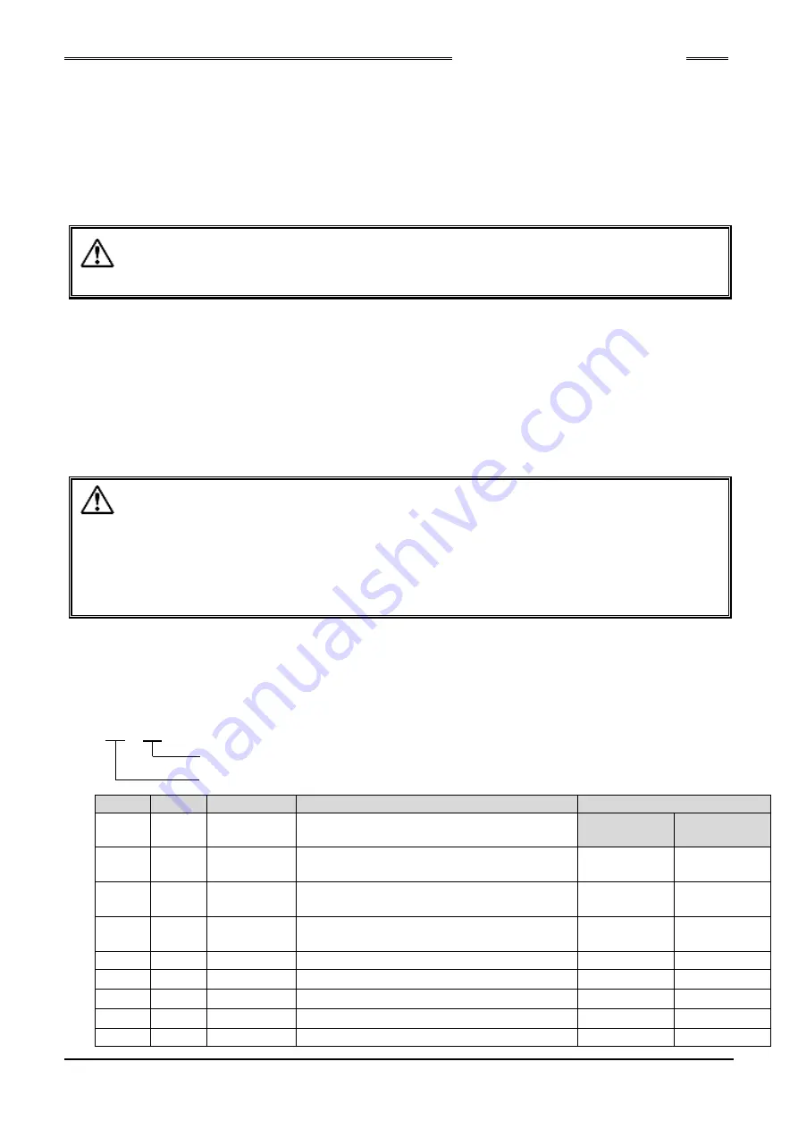
<Program Examples1>
Batch Sequence:
Six digits of data, which designate the parameter No. and the count (number of cycles) required for entering
the next stage, are used in each stage. The count is not incremented unless the fastening result is
ACCEPT.
0 2. 0 4.
0 0
Stage
D-No.
Data
Operation
PLC I/O Output Signal
-
580
1: Batch
Batch sequence is selected
BATCH OK
(TOTAL-OK)
BATCH
SEQ END
1
581
01.03.00
Fastening using parameter 1 (3 times).
ON after 3rd
fastening
-
2
582
02.04.00
Fastening using parameter 2 (4 times).
ON after 4th
fastening
-
3
583
07.01.00
Fastening using parameter 7 (1 time).
ON after 1st
fastening
ON after 1st
fastening
4
584
00.00.00
Batch sequence end.
-
-
5
585
00.00.00
-
-
-
6
586
00.00.00
-
-
-
7
587
00.00.00
-
-
-
8
588
00.00.00
-
-
-
Count
Fastening Parameter No.
Caution
Caution
Содержание Handheld Nutrunner HFC3000
Страница 2: ...www fec usa com Copyright 2017 FEC AUTOMATION SYSTEMS All Rights Reserved ...
Страница 14: ...Notes ...
Страница 15: ...Chapter 1 Outline PAGE 1 1 Chapter 1 Outline 1 ...
Страница 21: ...Chapter 2 Specifications PAGE 2 1 Chapter 2 Specifications 2 ...
Страница 28: ...Chapter 2 Specifications PAGE 2 8 Blank Page ...
Страница 29: ...Chapter 3 Sysytem Description PAGE 3 1 Chapter 3 System Description 3 ...
Страница 36: ...Chapter 3 System Description PAGE 3 8 Memo ...
Страница 37: ...Chapter 4 Installation and Wiring PAGE 4 1 Chapter 4 Installation Wiring 4 ...
Страница 67: ...Chapter 5 Power Up and Operational Tests PAGE 5 1 Chapter 5 Power Up and Operational Tests 5 ...
Страница 71: ...Chapter 6 Fastening Operation PAGE 6 1 Chapter 6 Fastening Operation 6 ...
Страница 151: ...Chapter 7 Troubleshooting PAGE 7 1 Chapter 7 Troubleshooting 7 ...
Страница 169: ...Chapter 8 Options PAGE 8 1 Chapter 8 Options 8 ...
Страница 181: ...Chapter 9 Fieldbus I O Interfaces PAGE 9 1 Chapter 9 Fieldbus I O Interfaces 9 ...
Страница 207: ...Chapter 9 Fieldbus I O Interfaces PAGE 9 27 9 3 2 Description of the hardware RUN LED ERROR LED CC Link Connector ...
Страница 229: ...Chapter 9 Fieldbus I O Interfaces PAGE 9 49 Blank Page ...
Страница 230: ......
Страница 231: ......


