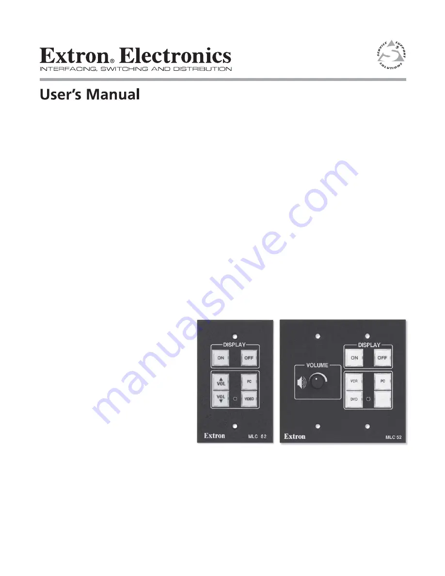
MLC 52 Series
MediaLink
™
Controllers
68-1079-01
Rev. C
04 06
im Vertrieb von
CAMBOARD Electronics
www.camboard.de
Tel. 07131 911201Fax 07131 911203
[email protected]
Страница 1: ...MLC 52 Series MediaLink Controllers 68 1079 01 Rev C 04 06 im Vertrieb von CAMBOARD Electronics www camboard de Tel 07131 911201 Fax 07131 911203 ce info camboard de ...
Страница 2: ...nd Bedienungsanleitungen genau durchlesen und verstehen Aufbewahren der Anleitungen Die Hinweise zur elektrischen Sicherheit des Produktes sollten Sie aufbewahren damit Sie im Bedarfsfall darauf zurückgreifen können Befolgen der Warnhinweise Befolgen Sie alle Warnhinweise und Anleitungen auf dem Gerät oder in der Benutzerdokumentation Keine Zusatzgeräte Verwenden Sie keine Werkzeuge oder Zusatzger...
Страница 3: ...for RS 232 control RS models only 2 11 Wiring for IR remote control 2 12 Wiring the IRL 20 2 13 Wiring the power connector 2 14 Wiring the VC faceplate 2 14 Mounting the MLC 52 2 15 Mounting the MLC to an electrical box or mounting bracket 2 15 Mounting the MLC to a wall or furniture 2 16 Chapter 3 Operation 3 1 Projector Control 3 2 Projector control memory 3 2 Front Panel Features and Operation ...
Страница 4: ...ff Confirmation 4 7 Configuring the MLC 52 for a power off confirmation 4 7 Application 3 Controlling Projectors That Have Multi coded IR Functionality 4 8 Configuring the MLC 52 for multi coded IR functionality 4 8 Projector remote control type A application 3 4 8 Programming RGB inputs type A remote control 4 8 Programming video inputs type A remote control 4 9 Issuing input selection commands l...
Страница 5: ...o mode 5 25 Removing a link from a button 5 25 Linking buttons in a series daisy chaining 5 25 Programming the MLC 52 for control by the IR 452 Remote 5 26 Removing commands from an IR 452 button 5 30 Performing IR Learning via software 5 30 Using the Advanced Projector Config tab 5 32 Creating a volume table 5 35 Buttons for the IR 452 accessible functions 5 38 Misc Options tab 5 39 Using emulati...
Страница 6: ... B 2 Standard MLC 52 IR and MLC 52 RS one gang size B 2 MLC 52 IR VC and MLC 52 RS VC two gang size B 3 Templates B 4 68 1079 01 Rev C 04 06 All trademarks mentioned in this manual are the properties of their respective owners im Vertrieb von CAMBOARD Electronics www camboard de Tel 07131 911201 Fax 07131 911203 ce info camboard de ...
Страница 7: ...ink Controller 1 Chapter One Introduction About the MLC 52 Series Features and Options MLC 52 Application Examples im Vertrieb von CAMBOARD Electronics www camboard de Tel 07131 911201 Fax 07131 911203 ce info camboard de ...
Страница 8: ...rchangeably in this manual to refer to all four models of the MediaLink controller unit regardless of which faceplate is attached to it The cabling operation and setup are identical for both models the models differ only in how they are controlled Standard features IR and RS 232 ports for universal projector control The MLC 52 has a dedicated port for communicating with virtually any projector or ...
Страница 9: ...wo one gang sized high impact plastic faceplates one black and one white that are durable enough for demanding environments The MLC 52 VC models include two two gang sized high impact plastic faceplates one black and one white Flexible mounting options With a standard electrical box or one of the included mounting brackets mud rings the MLC 52 can be mounted in a wide variety of locations includin...
Страница 10: ...ER OUTP UTS 4 8 Ohm s INPUTS L R L R REM OTE 10 V VO L MUT E L MPA 122 R C C US US PC DVD Projector VCR VGA w Audio Cable S video Audio RCA Composite Audio RCA Switched Audio Output Volume Control Extron MLC 52 RS VC Basic MediaLink Controller Extron MPA 122 Mini Power Amplifier Extron SPC 62 Ceiling Speakers in parallel IR or RS 232 Control DISPLAY OFF ON VCR PC DVD VOLUME MLC 52 Application diag...
Страница 11: ...MediaLink Controller 2 Chapter Two Installation Installation Overview UL Requirements Installation Procedures im Vertrieb von CAMBOARD Electronics www camboard de Tel 07131 911201 Fax 07131 911203 ce info camboard de ...
Страница 12: ...nd optional IR Link IR Emitters and or IRL 20 5 Connect power cords and turn on all the devices including the MLC 6 Configure the controller by using one of the following methods IR Learning See Configuring using IR Learning in chapter 3 Operations IR Data Transfer cloning See Configuring using data transfer in chapter 3 Operations Windows based configuration software program See Using the MLC 52 ...
Страница 13: ...LC will be mounted The templates provide measurements for installing the panel with either an electrical box or a mounting bracket The templates are not to scale and are provided for reference only The MLC 52 models include a one gang plastic faceplate which can be installed in a standard one gang sized electrical wall box that is at least 1 75 deep Mounting brackets mud rings are also included Th...
Страница 14: ...ter CAUTION If installing a metal faceplate do not remove the screws from the front of the faceplate 2 Lift the MLC off the faceplate 3 Place the MLC onto the new faceplate aligning the MLC s buttons with the openings in the new faceplate and the three screw holes in the MLC with the faceplate standoffs 4 Replace the three screws removed in step 1 and hand tighten them Refer to the MLM 52 1GWP and...
Страница 15: ...ng careful not to damage the circuits beneath it You may need to use the small screwdriver to gently pry the label out 5 Detach one of the preprinted labels or one of the blank labels from the label sheets included with the MLC 52 Remove the label from the backing and if applicable peel the protective film from the front of the label If you want to create customized labels you can use a label make...
Страница 16: ... out the wall furniture material inside the marked area 4 Check the opening size by inserting the wall box or mounting bracket into the opening The equipment should fit easily into the opening Enlarge or smooth the edges of the opening if needed 5 Feed cables through the wall box punch out holes and secure them with cable clamps to provide strain relief 6 Exposed cable shields braids or foil are p...
Страница 17: ...d with the bracket to attach the clips that fasten the bracket to the wall or furniture 8 If desired replace the faceplate and or button labels on the MLC See previous section 9 Cable and test the MLC before fastening it into the wall box mounting bracket or furniture Rear panel cable connections The following diagrams show the location of the connector switches LEDs and IR sensors located on the ...
Страница 18: ...r IR control of the MLC and for IR learning The two LEDs one for transmitting one for receiving send and receive IR signals enabling the MLC to learn commands and clone configurations from another MLC The IR remote control must be pointed directly at these LEDs for best results The MLC can learn IR commands in order to control the projector IR learning of projector control codes is necessary only ...
Страница 19: ...w shows the pin assignments of the MLC s control connector that are covered in detail on the following pages IR in 12V DC in F E D C B A RS 232 Tx RS Models Only IR out Pinout guide for the MLC 52 display source control connector The ports in this connector from left to right perform the following functions F Tx Transmits the RS 232 signal for projector control Although this port is present on bot...
Страница 20: ...riped wire only 12VDC output For the IR Broadcaster with emitter port For a wired projector remote port IR MLC 52 control connector IR MLC 52 control connector IR Demodulated IR Ground Demodulated IR Ground Modulated IR Ground 100 feet 30 5 m maximum Connect up to 2 IR Emitters max 70 283 01 Place the head of each IR Emitter over or directly adjacent to the controlled device s IR receiver To the p...
Страница 21: ...e Extron Web site D Ground F E D C B A F Transmit Tx To the display projector s RS 232 port RS 232 Wiring for RS 232 control RS models only Extron recommends using the UC 50 universal projector control cable for this connection One end of the cable is terminated with a female 9 pin D connector and the other end is unterminated The UC 50 pin assignments are as shown in the following illustration Re...
Страница 22: ...e other end Only three wires are required A MLC to A IR Link B MLC to B IR Link C MLC to D IR Link Connect the wires as shown in the illustration below Connectors are included with the IR Link but the cable must be purchased separately 4 Plug the 5 pole connector into one of the IR Link s communications connectors 5 Plug the 6 pole connector into the rear panel control port of the MLC 52 Wiring an...
Страница 23: ...ee appendix A for cable part numbers The maximum total distance between an Extron controller and the IRL 20 is 150 45 7 m 2 Attach a 3 5 mm 5 pole captive screw connector to the end of the cable that will be plugged into the IRL 20 3 Connect the wires on the other end of the cable to the provided 3 5 mm 6 pole captive screw connector A MLC to A IR Link B MLC to B IR Link C MLC to D IR Link Do not ...
Страница 24: ...y s polarity before connecting it to the MLC Wiring the VC faceplate If you have the MLC 52 IR VC or the MLC 52 RS VC controller it can be connected to an optional Extron MPA Mini Power Amplifier To set up this configuration wire the volume control potentiometer to the MPA as shown in the following diagram VOL MUTE 10V MPA 122 or MPA 181T Remote Port 10V 1 2 3 VOL MLC 52 VC Potentiometer Rear Pane...
Страница 25: ... the wall box or mounting bracket with the provided machine screws as shown in the following illustrations or attach it directly to the furniture with wood or metal screws If the MLC and the IR Link if applicable is not mounted to a grounded metal wall box Ground each faceplate directly to an earth ground or Tie each faceplate to its circuit board and power supply via a ground pin on one of the co...
Страница 26: ...r wall using wood screws If the MLC and the IR Link if applicable is not mounted to a grounded metal wall box Ground each faceplate directly to an earth ground or Tie each faceplate to its circuit board and power supply via a ground pin on one of the connectors Do not tie a product s faceplate to both a separate earth ground and the circuit ground via a connector pin If you tie a product to two di...
Страница 27: ...52 Using IR Using the MLC 52 VC Models with the MPA Series Power Amplifiers Powering the Projector Display On and Off Selecting Inputs Operating the MLC 52 Using IR Remote Control Resetting Locking the Front Panel Executive Mode im Vertrieb von CAMBOARD Electronics www camboard de Tel 07131 911201 Fax 07131 911203 ce info camboard de ...
Страница 28: ...ttings and configuration Front Panel Features and Operation The MLC 52 front panel contains six buttons each of which can be programmed with up to four IR or RS 232 commands functions It also contains a configuration port through which the MLC 52 can be connected to a PC s RS 232 port to program the MLC s buttons update firmware and save the MLC s current configuration to the PC s hard drive The t...
Страница 29: ...bled via the configuration software see Misc Options tab in chapter 5 Serial Communication 2 Input selection buttons These buttons are pre programmed to select input sources By default they operate as a switch group that is only one of the buttons may be selected at a time If you want these buttons to operate independently of each other use the Windows based control software to remove the group co...
Страница 30: ...selection or additional projector functions The volume buttons are pre labeled for convenience They can be changed to other labels that are provided See Replacing button labels in chapter 2 Installation for the procedure 5 Volume control knob MLC 52 IR VC and MLC 52 RS VC only The volume control knob on the VC models enables you to adjust the volume of the display device via the MPA power amplifie...
Страница 31: ...data transfer procedure 1 On the MLC from which the configuration will be transferred the donor unit set all configuration switches to off 2 On the MLC that will receive the data set switch 2 to on and all other switches to off 3 Position the two units so that the IR Transmit and Receive LEDs of both MLCs are facing each other and no more than 6 inches apart 1 1 2 3 4 E ON 2 3 4 Tx IR OUT GND IR I...
Страница 32: ...ly 17 of the data has been transferred the ON button lights brightly and remains lit to maximum brightness After another 17 has been transferred the OFF button lights to maximum brightness The buttons continue to light brightly in clockwise order after each increment of 17 of data has been transferred When a button becomes permanently lit the remaining buttons continue to blink in clockwise rotati...
Страница 33: ...ible To program the MLC via IR Learning follow these steps 1 Apply power to the MLC 52 2 On the rear panel set configuration switch 1 to on All front panel buttons should be dimly lit 3 Press the button on the MLC that will store the IR code that you want the MLC to learn The following takes place on the MLC The button that you pressed on the front panel begins to blink indicating that it is ready...
Страница 34: ...ation switch 1 on the rear panel to Off 7 Press the buttons that you configured to verify that the commands you entered have been learned An IR Emitter connected on the IR output should blink See Wiring for IR control in chapter 2 Installation Removing commands from a button If you want to delete a command that has been programmed onto a button you must remove all the commands programmed to that b...
Страница 35: ...tton with one command for each source up to four Only one button has to learn IR commands and it has enough memory blocks to learn four input selection commands To use this programmed button to select an input you must press it repeatedly to cycle through all the inputs until you reach the desired one To program a single button to select multiple inputs follow these steps 1 Disconnect power from t...
Страница 36: ... an MPA amplifier PO WER OUTP UTS 4 8 Ohm s INPUTS L R L R REM OTE 10 V VO L MUT E L MPA 122 R C C US US PC VGA with Audio DVD S video with Audio Projector VCR Composite Video with Audio Switched Audio Output MPA Volume Control Extron MLC 52 RS VC Basic MediaLink Controller with IR or RS 232 hardwired projector control Extron MPA 122 Mini Power Amplifier Extron SI 26X Ceiling Speakers in parallel ...
Страница 37: ...OUT GND IR IN GND 12V VOL MUTE 10V 1 1 2 3 4 E ON 2 3 4 POWER 12V 3A MAX OUTPUTS 4 8 Ohms INPUTS L R L R REMOTE 10V VOL MUTE L MPA 122 R C C US US Wiring an MLC 52 VC controller and an MPA series audio amplifier to a typical projector Audio is now controlled from the MPA instead of from the projector For best results ensure that the audio volume of the projector is set to maximum assuming that the...
Страница 38: ... See Using the Misc Options tab in chapter 5 Serial Communications for further information Selecting Inputs The four buttons below the Projector ON and OFF buttons on the MLC 52 front panel can configured to select inputs on the projector The PC and VIDEO buttons have been preconfigured to select inputs the desktop or laptop computer PC the VCR or DVD VIDEO Using IR Learning IR data transfer or th...
Страница 39: ...C 52 s optional hand held IR 452 remote control can be used in conjunction with the MLC 52 to operate your projector plasma display and input devices The IR 452 remote control is delivered with commands for a variety of device functions e g VCR On VCR Off Stop Pause etc These commands can be programmed onto the MLC s buttons only via the Windows based control software The IR 452 cannot control the...
Страница 40: ... panel controls for normal operation The controller responds to commands from the IR 452 as if the corresponding button were pressed on the controller From a distance of no more than 30 and within 40 degrees of the axis the IR 452 sends infrared IR signals to an MLC 52 via the optional IR Link IR signal repeater MLC 52 configuration cannot be performed from the IR 452 The IR 452 s Display Power bu...
Страница 41: ... the MLC 52 is in executive mode all front panel functions are locked so that pressing the buttons has no effect If a button is pressed while the MLC 52 is in executive mode all the front panel buttons blink indicating that the front panel is locked out Follow these steps to place the MLC in executive mode 1 Power off the projector or plasma display Executive mode cannot be enabled if the display ...
Страница 42: ...Operation cont d MLC 52 Series MediaLink Controller Operation 3 16 im Vertrieb von CAMBOARD Electronics www camboard de Tel 07131 911201 Fax 07131 911203 ce info camboard de ...
Страница 43: ...n 1 Using Multiple Sources with an MLC 52 Application 2 Projector Requiring a Power Off Confirmation Application 3 Controlling Projectors That Have Multi Coded IR Functionality im Vertrieb von CAMBOARD Electronics www camboard de Tel 07131 911201 Fax 07131 911203 ce info camboard de ...
Страница 44: ...be chosen Do not use a projector on which multiple video inputs share one audio input IR control If the projector is to be controlled by the MLC 52 using IR its IR remote control will have one of the following types of button configurations for video selection Projector remote control type A A different remote control button is used for each video input source Each button selects the input source ...
Страница 45: ...st be configured differently depending on the type of projector remote control that will be used and on whether the MLC will use IR or RS 232 projector control Because each button on the MLC 52 can store up to four commands per button the PC and VIDEO buttons on the MLC should be programmed as shown in the illustrations on pages 4 4 and 4 5 Configuring buttons for an IR controlled system The follo...
Страница 46: ...his enables you to switch between the two PC inputs by repeatedly pressing the PC button and between the two composite S video inputs by repeatedly pressing the VIDEO or blank button If you are using an MLC 52 IR or an MLC 52 RS one gang models with a type A remote configure the buttons using the following scheme MLC 52 PROJECTOR ON PC VIDEO OFF VOL VOL Command 1 RGB 1 Command 2 RGB 2 Command 1 Vi...
Страница 47: ... 1 Video IR command Command 1 S video IR command Configuring the MLC 52 IR VC and MLC 52 RS VC with a remote type A Projector remote control type B application 1 This remote control has only two input buttons one for the RGB inputs and one for the S video and composite video inputs Each of these buttons contains one command that causes the projector to toggle between inputs Program the command fro...
Страница 48: ...e blank and do not program Button should not be grouped Leave blank and do not program Button should not be grouped Configuring MLC 52 IR VC and MLC 52 RS VC with a remote type B Configuring buttons for multiple inputs on an RS 232 controlled system If the MLC 52 RS is to control the projector via RS 232 the projector remote control does not need to be involved Program the MLC buttons directly via...
Страница 49: ...C 52 can be configured so that the projector Power Off button does not need to be pressed twice for confirmation Using the macro mode feature you can send two power off commands sequentially from a single press of the MLC OFF button To configure the MLC OFF button to issue both a power off and a confirmation command follow these steps 1 Ensure that power is applied to the MLC 52 2 Set configuratio...
Страница 50: ...ng IR Learning to program multiple input selection commands onto the MLC 52 s buttons from two common types of hand held projector remote controls that have multi coded IR functionality For best results select a projector that has a dedicated audio and video input for each source used in the system Video inputs should not share the same audio input Projector remote control type A application 3 Thi...
Страница 51: ... command B for RGB 1 5 Program the input selection command B from the RGB 2 input selection button on the projector s hand held remote control into memory block 4 of the MLC 52 s PC button as follows a Press the PC button on the MLC front panel The button begins to blink indicating that the MLC is now ready to learn command B from the projector remote control s RGB 2 button On the rear panel the f...
Страница 52: ...ntrol into memory block 3 of the MLC 52 s VIDEO button as follows a Press the VIDEO button on the MLC front panel The button begins to blink indicating that the MLC is now ready to learn command B from the projector remote control s Video button On the rear panel the third LED up from the bottom should be flashing b Within 5 seconds while the VIDEO or blank button on the MLC 52 is blinking press t...
Страница 53: ...press memory block 1 The MLC 52 issues command A for RGB 1 input selection The projector switches to its RGB 1 input Second press memory block 2 The MLC 52 issues command A for RGB 2 input selection The projector switches to its RGB 2 input Third press memory block 3 The MLC 52 issues command B for RGB 1 input selection The projector switches to its RGB 1 input Fourth press memory block 4 The MLC ...
Страница 54: ...s and one for the S video and composite video inputs Each of these buttons contains two commands commands A and B that cause the button to toggle between inputs Following these steps use IR Learning to program the input selection commands from the projector s type B hand held remote control onto the MLC s PC and VIDEO or blank VC models buttons Programming RGB inputs type B remote control 1 Place ...
Страница 55: ...jector s remote control into memory block 1 of the MLC 52 s VIDEO or blank for VC models button as follows a Press the VIDEO button on the MLC front panel The button begins to blink indicating that the MLC is now ready to learn command A from the projector remote control s Video button On the rear panel the bottom IR Learning LED should be flashing b Within 5 seconds while the VIDEO button on the ...
Страница 56: ...ojector remote type B Issuing input selection commands learned from remote control type B The MLC now has two commands each on the PC and VIDEO buttons When you press an MLC input button repeatedly the following commands are issued Using the PC button RGB First press memory block 1 The MLC 52 issues command A for RGB input selection Second press memory block 2 The MLC 52 issues command B for RGB i...
Страница 57: ...UTER MLC 52 DISPLAY ON PC OFF DVD VCR VOLUME Command 1 Computer IR Command A Command 2 Computer IR Command B Leave blank and do not program The button should not be grouped Leave blank and do not program The button should not be grouped Command 1 Video 1 IR Command A Command 2 Video 2 IR Command B Label button accordingly and place it in group Projector Remote Type B Configuring an MLC 52 VC model...
Страница 58: ...Special Applications cont d MLC 52 Series MediaLink Controller Special Applications 4 16 im Vertrieb von CAMBOARD Electronics www camboard de Tel 07131 911201 Fax 07131 911203 ce info camboard de ...
Страница 59: ...roller 5 Chapter Five Serial Communication Using the MLC 52 Configuration Program Using Simple Instruction Set SIS commands im Vertrieb von CAMBOARD Electronics www camboard de Tel 07131 911201 Fax 07131 911203 ce info camboard de ...
Страница 60: ...otocol 9600 baud 8 bits 1 stop bit Parity None Flow control None Using the MLC 52 Configuration Program To perform advanced configurations e g removing a button from a switch rotation updating firmware and using display drivers you must use the included Extron Windows based configuration software The MLC 52 Configuration program s graphical user interface includes the same functions as those on th...
Страница 61: ...ink Help Program provides information on settings and on how to use the configuration program itself Some features including the miscellaneous options are available only via this configuration program These features are described in the sections of this chapter that correspond to the parts of the configuration program where the features are found 1 To run the configuration program do either of the...
Страница 62: ...the buttons on all of the MLC 52 models are configured by the same methods Advanced Projector Config Enables you to enter user defined RS 232 commands define parameters for projector volume control and change the name of the projector driver Misc Options MLC 52 RS only Lets you adjust baud rates data bits parity bits and warm up and cool down times for the projector Two pull down menus File menu P...
Страница 63: ...t load the appropriate driver for your projector or plasma display to the MLC 52 IR drivers are loaded via the MLC 52 Configuration program as part of the process to program MLC buttons RS 232 drivers must be loaded selected prior to choosing RS 232 commands to program the buttons See Loading Extron drivers for RS 232 communication later in this chapter The MLC 52 is compatible with IP Link IR dri...
Страница 64: ...functions to buttons using RS 232 drivers section later in this chapter Viewing the IP Link IR package version To find out the version number of the IP Link IR package that you have do the following 1 Open the MLC 52 configuration program 2 Click Help on the menu bar to display the Help menu The item DriverBase Version n gives the IP Link IR package version IR drivers are stored at the following l...
Страница 65: ...e software shows a one gang sized model on this tab However the buttons on all of the MLC 52 models are configured by the same methods The Programming Legend below the MLC 52 diagram shows the following A green dot on a button in MLC 52 or the IR 452 diagram indicates that an RS 232 code has been associated with one of that button s memory blocks A red dot on a button indicates that an IR code has...
Страница 66: ...LC 52 buttons Saving and restoring the configuration Before downloading drivers or programming buttons you may want to save the MLC 52 s current configuration in case you want to restore those settings in the future Saving a configuration 1 From the File menu select Save CONFIGURATION as File menu The Save Current MediaLink Configuration as window opens 2 If necessary browse to locate the folder i...
Страница 67: ...ect Restore CONFIGURATION from The following confirmation prompt opens Restoring configuration confirmation prompt 2 Click OK The Restore Saved MediaLink Configuration from window opens 3 If necessary browse to locate the configuration file that you want to restore Configuration files are usually stored in the MediaLink folder 4 Select the desired configuration file It must have the extension mlk ...
Страница 68: ...to one of these memory blocks its circle becomes red for IR commands or green RS 232 commands PC button selected on Controller MLC Config tab When you select the button the following occurs on the screen The selected button turns pale yellow surrounded by a square black border The Button field in the upper left corner of the tab displays the name of the button that was selected Radio buttons for t...
Страница 69: ...asma display Device Models Model name number of your projector or other display device When you select a model the fields below the Device Models section display the selected driver s version and origin Status Released The driver was created by Extron User Learned The driver was created by a user or another non Extron person Functions Available in Driver Functions that the selected button can be p...
Страница 70: ...he same button select the next Cmd radio button then repeat steps 3 and 4 For each button you can perform this procedure up to four times until the button s four memory blocks are all assigned You must program the next command in order You cannot for example program memory block 1 Cmd 1 radio button then skip to block 3 or 4 For IR commands you can mix driver functions from different devices on th...
Страница 71: ...ER from File menu 2 The following confirmation prompt window appears MediaLink Control confirmation prompt for loading a driver On this window do one of the following If this is the first time you will be configuring the MLC 52 with the configuration software follow these steps to load a driver a Click No There is no configuration to save The Build MediaLink Configuration from window opens b Open ...
Страница 72: ...s takes approximately 30 seconds If you have used the MLC 52 configuration program previously to configure the MLC 52 and you want to save your current configuration before loading a new driver to replace the existing one follow these steps a Click Yes on the confirmation prompt window The Save Current MediaLink Configuration as window opens b If necessary browse to locate the folder in which you ...
Страница 73: ... are preconfigured with the appropriate commands from the driver If the VOL UP and VOL DWN buttons will not be used for volume control remove the commands from them See Removing commands from a button later in this chapter When you select the button the following occurs on the screen The selected button turns yellow surrounded by a square black border The Button field in the upper left corner of t...
Страница 74: ...ivers for RS 232 communication earlier in this chapter for the procedure 3 From the Functions Available in Driver list box on the Driver Selection window select the function that you want to program onto the button Driver Selection window for RS 232 4 Click the Take Button Config button to implement your selections The command is programmed into the button s selected memory block The following cha...
Страница 75: ... assign another command to the same button select the next Cmd radio button then repeat steps 3 and 4 For each button you can perform this procedure up to four times until the button s four memory blocks are all assigned For RS 232 you can not mix driver functions from different devices on the same button Only one RS 232 driver can be used at a time 6 When finished programming commands to the butt...
Страница 76: ... Actions field click one of the following buttons One Command Removes the command only from the selected memory block If you want to remove only one command at a time you must remove the commands in descending order e g remove command 4 before removing commands 3 2 and 1 All Commands in Button Removes all the commands from all the memory blocks on the button Remove IR 232 Codes buttons A prompt wi...
Страница 77: ...ase Volume or Decrease Volume If you press and hold a volume control button the projector increases or decreases the volume steadily until you release it or it reaches its limit Volume table The volume level is set by issuing commands each of which correlates to a specific number in a table of values For example a projector may have a volume table that ranges from 0 to 100 Therefore more than two ...
Страница 78: ...move the table in order to continue programming the button Removing the table removes all commands from the volume buttons you do not need to do anything else If you later want to restore the table management to the button reload the driver to the MLC If the projector does not have a volume table you must use the Remove IR 232 Commands buttons to remove the volume commands from the button you want...
Страница 79: ... By default the buttons are in toggle mode meaning that each time the button is pressed one of its programmed commands is issued Each button can store up to four commands When a button is in macro mode one press executes all the commands programmed onto that button in the order they were programmed at 1 5 second intervals One example of a button macro application would be turning on multiple proje...
Страница 80: ...to the button prior to setting it for macro mode Linking buttons to create macros Linking gives you an additional way to create button macros It provides a way to associate MLC 52 buttons with each other Using the MediaLink MACRO Configuration screen you can link a memory block of one button to a memory block of another button Once two buttons are associated you can press one button to trigger its...
Страница 81: ...LC button s four memory blocks If a button memory block has been programmed with an IR code it is shown in red if it has an RS 232 code it is shown in green Other items of interest on the screen include Trash can icon Dragging a linked button from the Trigger section to this icon removes the link from the button Return button Click this button to return to the Controller MLC Config screen Follow t...
Страница 82: ... block A dropdown menu appears also giving you options for the amount of delay between execution of the trigger button s command and that of the destination button See the illustration below MediaLink MACRO Configuration screen with the delay times dropdown menu displayed 4 Select the length of delay that will occur between when the trigger button s command is sent and when the destination button ...
Страница 83: ...e button s memory block buttons from the Trigger section to the target memory block button under Destination When you press the trigger button it issues all its macro commands then the command on the button to which it is linked Removing a link from a button 1 Click and drag the linked trigger memory block button to the trash can icon at the bottom of the Macro screen and release the button 2 From...
Страница 84: ...tual buttons The procedure for programming IR 452 button commands is similar to the way you program commands on the MLC 52 buttons in the left section of the tab In order to use the IR 452 remote with the MLC 52 you must install the IR Link or IRL 20 and connect it to the MLC See Wiring for IR remote control in chapter 2 You cannot configure the MLC 52 from the IR 452 Remote Control To program the...
Страница 85: ... CMD radio buttons at the top of the tab Cmd 1 through Cmd 4 also represent the memory blocks for the remote buttons The radio button for the memory block you are currently programming is selected Switch Mode and Actions buttons are displayed in a column down the center of the tab 3 In the Actions section click the Pick IR Driver Functions or the Pick 232 Driver Functs button depending on the type...
Страница 86: ...ust programmed is surrounded by a red field for an IR command or a green field for an RS 232 command In the following example an IR command was added Driver Selection window showing that IR 452 memory block 1 Cmd 1 contains an IR red command 6 If you want to assign another command to the same button select the next Cmd radio button on the Driver Selection window and repeat steps 4 and 5 For each b...
Страница 87: ...eld for an RS 232 command In the example above an IR command was programmed in memory block 1 Cmd 1 A dot appears on the button to indicate that it contains commands If the button s first programmed memory block contains an IR command the dot is red If the button s first memory block contains an RS 232 command the dot is green In the same example the MUTE ON button now contains an IR command IR 45...
Страница 88: ...tton A confirmation prompt window appears 4 Click OK The specified command s are removed from the selected button On the screen the red or green field is removed from around the Cmd radio button s Performing IR Learning via software The MLC 52 can learn commands from your projector s remote control in order to control the projector or devices such as VCRs or DVD players Using IR Learning you can p...
Страница 89: ...wing dialog box opens indicating the button to which IR codes will be learned and to allow you to OK or cancel the IR learning process 7 When you are ready to start click OK A Status of IR Learning message area appears beneath the Actions field instructing you to aim the projector remote control and press the button whose function you want the MLC to learn im Vertrieb von CAMBOARD Electronics www ...
Страница 90: ...at steps 2 through 8 for each button to be set up with IR codes 10 Place configuration DIP switch 1 back in the Off position All four switches should be down Using the Advanced Projector Config tab The Advanced Projector Config tab shown on the next page provides a way to check the type length and location of codes IR and RS 232 if any that are stored in the memory blocks for the MLC buttons On th...
Страница 91: ...the following 1 In the top section of the tab click on the diagram of the button that you want to program with RS 232 commands In the example below the PC button has been selected Input selection button representations 2 Select the Cmd radio button for the button memory block that you want to program 3 In the Sends field select the RS 232 radio button if it is not already selected Sends radio butt...
Страница 92: ... are entered in pairs of characters ASCII commands are entered in single characters See your projector s user manual for the available commands As you enter text in the small box for the first time the characters you enter are also inserted in the large box in front of the small rectangle With each subsequent entry you make the rectangle moves to the next position indicating the insertion point fo...
Страница 93: ...ume for example as opposed to a pair of volume up down commands you can program those commands in the Volume Table section Use the volume table only if you plan to use the display device s audio inputs When you click the Volume Table button on the Advanced Projector Config tab slider bars and buttons are displayed by enabling you to set volume adjustment step parameters You can do this either by d...
Страница 94: ...step before you perform the rest of this procedure Once you begin making entries for the volume table the Max step size field is locked and you are unable to change your selection 4 Use the Total Steps slider to set the total number of volume adjustment steps that will be in the volume table 5 In the Bytes field below the Sends field set the scroll bar for the number of bytes that will be in the f...
Страница 95: ... you enter the next byte of the command in one of the small boxes 7 Repeat step 6 until you have programmed all the bytes for the first step The example on the next page shows the command for the first step of a volume table Example of a Step 1 command of a volume table 8 Enter command strings for the rest of the steps in your volume table If most of the steps for volume increments in your table h...
Страница 96: ...lume table you must clear the Use for VOLUME control check box on the Controller Config MLC tab To remove a volume table from the MLC see Removing commands from a button earlier in this chapter Buttons for the IR 452 accessible functions The Display Mute Display UnMute DVD and VCR buttons on the Advanced Projector Config tab can be programmed with commands that must be transmitted to the MLC via t...
Страница 97: ...Options tab contains the following fields Pwr UP Delay and Pwr Dn Delay You can move these two sliders to select the number of seconds 0 to 300 that the projector will take to warm up delay powering on or cool down delay powering off after a Projector On or Off button is pressed Auto shutoff If the Auto shutoff check box is selected the MLC monitors the time elapsed since the last button press and...
Страница 98: ...y Power Off If this check box is selected no IR or RS 232 codes are sent to the projector while it is powered off warming up or cooling down except for the command to power on Bypass Power down button 2 second Holdoff When this check box is cleared the default in order to power off the projector you must press and hold the power off button for 2 seconds after which the OFF button starts to blink a...
Страница 99: ...isting setup If you will be creating a brand new configuration click Cancel on the Initialize Emulated MediaLink Configuration from window The emulated system starts out with the MLC 52 default settings If you want to create a configuration based on an existing configuration file one that was previously saved select the desired configuration ___ MLK file Click Open im Vertrieb von CAMBOARD Electro...
Страница 100: ...g the configuration settings it must have a mlk extension then click Save The MediaLink EMULATION MODE Configuration dialog box appears as shown below 5 Select the MLC 52 model RS or IR that you are configuring then click OK The MLC 52 main screen appears with EMULATION MODE at the bottom im Vertrieb von CAMBOARD Electronics www camboard de Tel 07131 911201 Fax 07131 911203 ce info camboard de ...
Страница 101: ...e the configuration emulation for future use follow steps 1 and 2 in Saving and restoring configurations earlier in this chapter Uploading firmware If the need arises you can update the MLC 52 s firmware via RS 232 Visit the Extron Web site www extron com and check for firmware updates which you can download After you have downloaded the new firmware file to your PC follow these steps to upload it...
Страница 102: ... extracted to the following location c Program Files Extron Firmware MLC 52 vxxx s19 where is an alphanumeric character and xxx is the firmware version number Firmware update files have a s19 extension make sure that the Files of type field is set to s19 Upload file from window 5 Click Open The firmware update file is uploaded to your MLC During the process the Firmware Loader window indicates the...
Страница 103: ...on switcher front panel selection or adjustment takes place the MLC responds by sending a message to the host No response is required from the host The MLC initiated messages are listed here underlined C Copyright 2005 Extron Electronics MLC 52 V1 00 The MLC sends the copyright message when it first powers on Error responses When the MLC receives a valid SIS command it executes the command and sen...
Страница 104: ...Space Esc Escape key X1 Firmware version number X XX format X2 Display power status 0 through 3 0 display power is off 1 display power is on 2 display is cooling down 3 display is warming up X3 On off status 0 off disabled 1 on enabled Memory block number in hexadecimal where can be 0 to 7F hex 0 to 127 decimal d Memory block number in ASCII numeric notation Commands are not case sensitive unless ...
Страница 105: ...30 50 Pwr 0 View display power status P 50 Pwr X2 X2 display power status 1 on 0 off 2 display cooling down 3 display warming up Example P 5 0 Pwr2 The projector display is cooling down Reset Reset switches to factory default Esc zXXX 1B 7A 58 58 58 0D ZapX Reset all switches and buttons to the factory default and erase any codes added by the user Front panel lockout executive mode Unlock 0X 30 58...
Страница 106: ...ve 1B A3 0D 16k bytes of data The MLC sends 16k bytes of binary data to the host Send receive a segment 256 bytes of data a segment relating to a single button Send 1B 2B A6 256 bytes of data Seg0 The host sends 256 bytes of binary data to the MLC Receive 1B A7 0D 256 bytes of data The MLC sends 256 bytes of binary data to the host Initiate or abort IR learning Start learning 1B B0 0D LrnRdy Initi...
Страница 107: ...ink Controller A Appendix A Specifications Part Numbers and Accessories Specifications Part Numbers and Accessories im Vertrieb von CAMBOARD Electronics www camboard de Tel 07131 911201 Fax 07131 911203 ce info camboard de ...
Страница 108: ...t IR control TTL level 0 to 5 V modulated infrared control from 30 kHz up to 60 kHz IR learning frequencies 30 kHz to 62 kHz IR learning distance 4 10 cm to 14 36 cm from the side panel Control peripheral equipment MLC 52 RS VC MLC 52 IR VC Control port for 10k ohms control 1 3 5 mm direct insertion captive screw connector 3 pole Pin configuration 1 reference voltage input 2 variable voltage outpu...
Страница 109: ... captive screw connector Tweeker small screwdriver MR100 1 gang plastic mounting brackets mud rings 1 black 1 white 70 519 12 13 MR200 2 gang plastic mounting brackets mud rings 1 black 1 white 70 519 22 23 MLC 52 MediaLink Controller User s Manual on CD ROM MLC 52 MediaLink Controller Quick Start Guide 52 Quick Start Guide 68 627 01 Product weight MLC 52 RS MLC 52 IR 0 2 lb 0 1 kg MLC 52 RS VC ML...
Страница 110: ... 52 VC metal black white 70 538 02 03 Miscellaneous accessories Part number MPA122 Mini PowerAmplifier 60 668 01 MPA181T Mini PowerAmplifier 60 747 01 IR Link IR signal repeater black white 60 404 02 03 IRL 20 60 580 01 VC 50 70 530 02 WP 120 Composite Video and Stereo Audio Wall Plate black white 60 431 12 22 WP 130 S video and Stereo Audio Wall Plate black white 60 430 12 22 WP 150 Computer Vide...
Страница 111: ...100 feet 30 5 meters long 26 461 02 200 feet 61 meters long 26 461 03 400 feet 122 meters long 26 461 04 Bulk 500 feet 152 4 meters long plenum 22 119 02 Bulk 1000 feet 304 8 meters long plenum 22 119 03 Bulk 500 feet 152 4 meters long non plenum 22 148 02 Bulk 1000 feet 304 8 meters long non plenum 22 148 03 im Vertrieb von CAMBOARD Electronics www camboard de Tel 07131 911201 Fax 07131 911203 ce...
Страница 112: ... Numbers and Accessories cont d MLC 52 Series MediaLink Controller Specifications Part Numbers and Accessories A 6 im Vertrieb von CAMBOARD Electronics www camboard de Tel 07131 911201 Fax 07131 911203 ce info camboard de ...
Страница 113: ...MLC 52 Series MediaLink Controller B Appendix B Dimensions and Templates Dimensions Templates im Vertrieb von CAMBOARD Electronics www camboard de Tel 07131 911201 Fax 07131 911203 ce info camboard de ...
Страница 114: ...62 THRU 296 7 518 X 82 178 4 521 THRU 278 7 061 X 90 FAR SIDE A A 030 0 762 85 ALL AROUND R 070 R1 778 ALL AROUND 000 0 000 3X 538 13 665 125 3 175 000 0 000 715 18 161 1 140 28 956 1 315 33 401 1 550 39 370 2 065 52 451 000 0 000 2X 1 088 27 635 3 313 84 150 2X 3 963 100 656 2X 4 288 108 920 150 3 806 1 150 29 214 1 390 35 306 1 630 41 398 2 630 66 806 4 X R 031 0 787 R 015 0 379 AROUND ALL RECTA...
Страница 115: ...1 3 192 2 238 2 062 1 613 2X 1 303 2X 1 088 2X 610 000 869 1 919 4 600 2X 2 992 2X 3 422 2X 4 042 3 882 4X 3 205 2 532 2X 2 372 3X 1 395 000 Ø 500 2X MLC 52 125 THRU 240 X 82 3X Ø 178 THRU Metal 100 156 THRU 295 X 82 Plastic 110 MLC 52 VC dimensions im Vertrieb von CAMBOARD Electronics www camboard de Tel 07131 911201 Fax 07131 911203 ce info camboard de ...
Страница 116: ...eference only The controller requires a depth of at least 1 25 3 2 cm inside the wall or furniture If you use a wall box or mud ring connect it to an earth ground If you do not use a grounded wall box or mud ring ground the faceplate to an earth ground or tie it to the circuit ground via a ground pin on the circuit board MLC 52 Front view Cut Out Template for Extron s 4 50 11 43 cm To install MLC ...
Страница 117: ... install MLC 52 VC directly into furniture or wall cut along this line Top Panel 2 91 7 40 cm 3 50 8 90 cm SURFACE CUT OUT AREA FOR FURNITURE MOUNT Location of MLC 52 4 50 11 43 cm MLC 52 IR VC and MLC 52 RS VC cutout template im Vertrieb von CAMBOARD Electronics www camboard de Tel 07131 911201 Fax 07131 911203 ce info camboard de ...
Страница 118: ...Dimensions and Templates cont d MLC 52 Series MediaLink Controller Dimensions and Templates B 6 im Vertrieb von CAMBOARD Electronics www camboard de Tel 07131 911201 Fax 07131 911203 ce info camboard de ...
Страница 119: ...Electronics Beeldschermweg 6C 1001 East Ball Road 3821 AH Amersfoort Anaheim CA 92805 USA The Netherlands Asia Japan Extron Electronics Asia Extron Electronics Japan 135 Joo Seng Road 04 01 Kyodo Building PM Industrial Bldg 16 Ichibancho Singapore 368363 Chiyoda ku Tokyo 102 0082 Japan This Limited Warranty does not apply if the fault has been caused by misuse improper handling care electrical or ...
Страница 120: ...he Netherlands 31 33 453 4040 Fax 31 33 453 4050 Extron Electronics Asia 135 Joo Seng Road 04 01 PM Industrial Building Singapore 368363 65 6383 4400 Fax 65 6383 4664 Extron Electronics Japan Kyodo Building 16 Ichibancho Chiyoda ku Tokyo 102 0082 Japan 81 3 3511 7655 Fax 81 3 3511 7656 www extron com im Vertrieb von CAMBOARD Electronics www camboard de Tel 07131 911201 Fax 07131 911203 ce info cam...