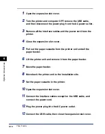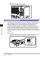
6-28
Optional Accessor
ies
6
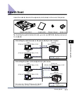
Network Board
5
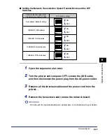
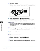
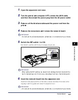
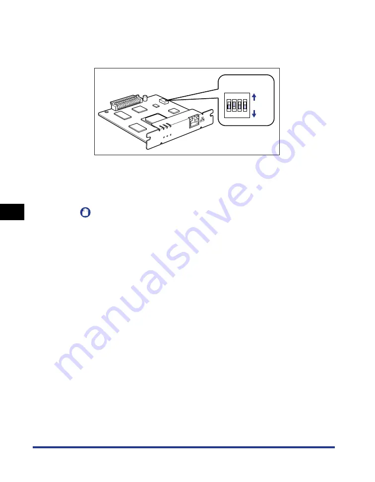
Set the DIP switches.
Set the DIP switches with the tip of a ball-point pen etc. For details on methods
for setting the DIP switches, see the table of p. 6-27.
6
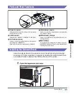
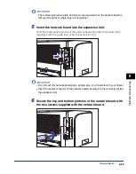
Insert the network board into the expansion slot.
Hold the metal panel portions of the network board and insert the board while
aligning it with the guide rails inside the expansion slot.
IMPORTANT
•
Do not touch the network board parts, printed wire, or connectors with your hands.
•
Insert the printer connector of the network board securely into the connector inside
the expansion slot.
7
Secure the top and bottom portions of the network board with
the two screws supplied with the network board.
8
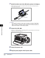
Connect the LAN cable.
9
Connect the power cord.
10
Plug the power plug into the AC power outlet.
11
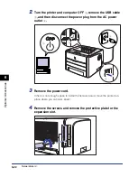
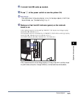
Connect the USB cable, then close the expansion slot cover.
ERR LNK 100
NB-C1
ON
OFF
OFF
1
2
3
4
DIP switches
Содержание laser Shot LBP 3300
Страница 2: ...LBP3300 Laser Printer User s Guide ...
Страница 25: ...xxii ...
Страница 45: ...1 20 Before You Start 1 Connecting to a Computer ...
Страница 90: ...2 45 Loading and Outputting Paper 2 Setting Up the Printer Driver and Printing 7 Click OK to start printing ...
Страница 99: ...2 sided Printing 2 54 Loading and Outputting Paper 2 12 Click OK to start printing ...
Страница 105: ...2 sided Printing 2 60 Loading and Outputting Paper 2 ...
Страница 305: ...5 32 Routine Maintenance 5 Handling the Printer ...
Страница 391: ...7 52 Troubleshooting 7 Confirming the Printer Features ...
Страница 397: ...8 6 Appendix 8 Dimensions of Each Part Paper Feeder Unit PF 35 117 4 116 6 369 7 421 1 mm ...
Страница 411: ...8 20 Index Appendix 8 V Ventilation Slots 1 4 W Watermark 4 28 4 51 When Nothing is Printed 7 37 Windows Firewall 8 10 ...
Страница 413: ...8 22 Appendix 8 Location of the Serial Number ...
Страница 414: ...R IE 700AC CANON INC 2005 ...

