■ To reinstall and verify the imagePASS
1. Reseat all boards, cables, connectors, and other parts loosened or removed during service.
When routing cables in the imagePASS make sure that:
• Covers are securely installed after routing cables.
• Cables are not looped around circuit boards or components (such as capacitors and resistors).
• Cable routing does not interfere with the operation of internal components.
• Cables do not lie on or against any internal heating element.
• Cables do not interfere with removing or replacing components.
• Cables do not interfere with opening or closing imagePASS panels.
• Cables are not tangled.
• Cable slack is secured with a tie-wrap.
IMPORTANT:
Improper connection of the internal power cables can damage the imagePASS. See
“To check cable connections” on page 17
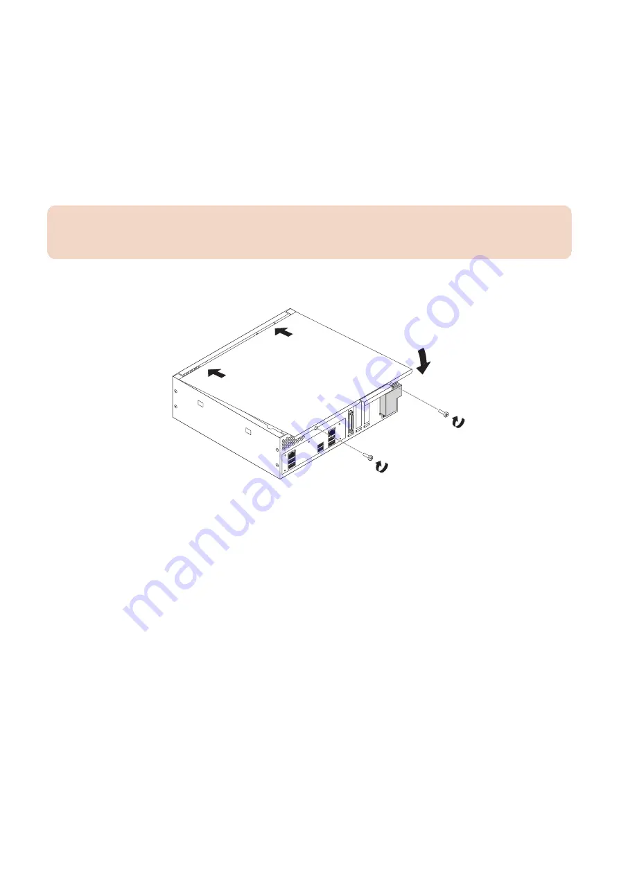
2. Replace the cover on the imagePASS.
Make sure that all cables are fully inside the chassis before you replace the cover. Slide the cover until it engages the edge
of the chassis opposite the connector panel, and then lower the cover.
Figure 29: Replacing the chassis cover
3. Replace the two screws that you removed earlier.
Tighten the screws to secure the cover to the imagePASS.
4. Reinstall the imagePASS on the side of the printer.
For detailed information about removing/installing the printer, see the installation instructions that accompany the printer (not
included in this service guide).
5. Connect the external cables that you removed during inspection or service.
Be sure to properly connect the following cables (see
“imagePASS connector panel and LED diagnostic codes” on page
).
• Network cable
• Crossover Ethernet cable between the imagePASS and printer
• Printer interface cable
• imagePASS power cable
6. If you installed a new HDD, install system software (see
“Installing System Software” on page 40
A spare HDD is shipped without preinstalled system software.
7. Make sure to configure the date and time in Setup (see
“To configure the system date and time” on page 22
).
8. Before you leave the customer site, verify the imagePASS operation.
• Connect the imagePASS to the network (see
“imagePASS connector panel and LED diagnostic codes” on page 14
).
• Ask the site administrator to check the Setup options (see Configuration and Setup).
3. REPLACING PARTS
38
Содержание imagePASS-P2
Страница 1: ...Revision 1 1 imagePASS P2 Service Manual ...
Страница 6: ...Introduction 1 Introduction 2 Specifications 6 ...
Страница 13: ...Using the imagePASS 2 Using the imagePASS 9 ...
Страница 16: ...Figure 3b The imagePASS Tools menu 2 Using the imagePASS 11 ...
Страница 17: ...REPLACING PARTS 3 Replacing Parts 13 ...
Страница 44: ...INSTALLING SYSTEM SOFTWARE 4 Installing System Software 40 ...
Страница 64: ...TROUBLESHOOTI NG 5 Troubleshooting 60 ...
Страница 84: ...2 Stepped Screw M4 2x 3 4x Screw with Toothed Washer M4x8 Stepped Screw M4 4 4x 8x 6 INSTALLATION PROCEDURE 79 ...
Страница 87: ...2 2x Stepped Screw M4 3 Screw with Toothed Washer M4x8 Stepped Screw M4 6x 4 4x 8x 6 INSTALLATION PROCEDURE 82 ...
Страница 88: ...5 4x Screw with Toothed Washer M4x8 6 Crossover Ethernet Cable 1x 2x 7 2x 8 2x 6 INSTALLATION PROCEDURE 83 ...


